
Related Manuals for Contec AI-1664LAX-USB


Summary of Contents for Contec AI-1664LAX-USB
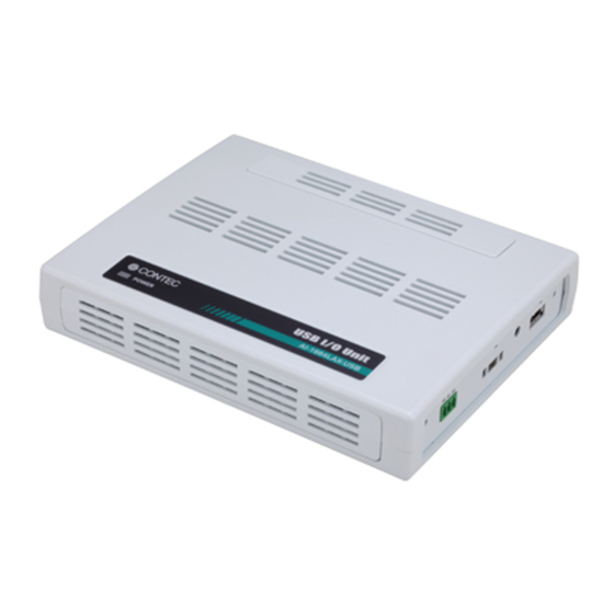
- Page 1 PC-HELPER 100KSPS 16-bit Analog Input Unit for USB AI-1664LAX-USB User’s Guide CONTEC CO., LTD.
-
Page 2: Check Your Package
Check Your Package Thank you for purchasing the CONTEC product. The product consists of the items listed below. Check, with the following list, that your package is complete. If you discover damaged or missing items, contact your retailer. Product Configuration List - Unit [AI-1664LAX-USB] …1... -
Page 3: Trademarks
No part of this document may be copied or reproduced in any form by any means without prior written consent of CONTEC CO., LTD. CONTEC CO., LTD. makes no commitment to update or keep current the information contained in this document. The information in this document is subject to change without notice. -
Page 4: Table Of Contents
Setting with the Found New Hardware Wizard ................17 Setting Properties Using Device Manager ..................18 Step 4 Checking Operations with the Diagnosis Program ..............20 What is the Diagnosis Program?....................... 20 Check Method ............................ 20 Using the Diagnosis Program ......................21 AI-1664LAX-USB... - Page 5 Counter Function ............................60 1. Setting the Operating Conditions ....................60 2. Starting/Stopping Operation ......................61 3. Monitoring the Status and Acquiring Data.................. 61 4.Reset..............................62 Digital Input Function..........................63 Digital Output Function ..........................64 ABOUT HARDWARE Hardware specification ..........................65 AI-1664LAX-USB...
- Page 6 Physical dimensions ..........................67 Block Diagram ............................68 Control Signal Timings ..........................69 Control Signal Timings for Analog Input ..................69 Control Signal Timings for Counter....................70 About Calibration ............................71 Difference from AI-1664LA-LPE and AD16-64(LPCI)LA ..............72 AI-1664LAX-USB...
- Page 7 AI-1664LAX-USB...
-
Page 8: Before Using The Product
A digital filter is included to prevent misdetection due to chattering on the control signal (external trigger input signal, sampling clock input signal, etc.), digital input signal and counter input signal. (except from external clock input signal and counter gate signal) AI-1664LAX-USB... - Page 9 AD16-64(LPCI)LA” *2 This product cannot be stacked up for installation. *3 Do not connect the device other than that of CONTEC’s USB to the USB port included on the AI- 1664LAX-USB. Otherwise, this may cause a failure or malfunction. *4 When connecting multiple units with USB HUB function and set up them, do one at a time and complete setup for the previous unit before starting to do the next unit.
-
Page 10: Support Software
1. Before Using the Product Support Software You should use CONTEC support software according to your purpose and development environment. Windows version of analog I/O driver API-AIO(WDM) [Stored on the bundled CD-ROM driver library API-USBP(WDM)] The API-AIO(WDM) is the Windows version driver library software that provides products in the form of Win32 API functions (DLL). -
Page 11: Cable & Connector (Option)
*6 It is the same as the one appended to the product. Please buy it necessary for maintenance. For details on the range channels available to each terminal panel, see Figure 3.2 "Connecting example of option". Check the CONTEC’s Web site for more information on these options. AI-1664LX-USB... -
Page 12: Customer Support
You can download updated driver software and differential files as well as sample programs available in several languages. Note! For product information Contact your retailer if you have any technical question about a CONTEC product or need its price, delivery time, or estimate information. Limited One-Year Warranty CONTEC products are warranted by CONTEC CO., LTD. -
Page 13: Safety Precautions
Make sure that your PC can supply ample power to all this product connected. Insufficiently energized products could malfunction, overheat, or cause a failure. Do not connect the device other than that of CONTEC’s USB to the USB port included on the AI- 1664LAX-USB. Otherwise, this may cause a failure or malfunction. - Page 14 FCC WARNING Changes or modifications not expressly approved by the party responsible for compliance could void the user's authority to operate the equipment. AI-1664LAX-USB...
-
Page 15: Environment
1. Before Using the Product Environment Use this product in the following environment. If used in an unauthorized environment, the product may overheat, malfunction, or cause a failure. Operating temperature 0 - 50°C Operating humidity 10 - 90%RH (No condensation) Corrosive gases None Floating dust particles... -
Page 16: Setup
Connecting the Product Setting Properties Using Installing the Software - Connection with 5VDC Device Manager - API-USBP(WDM) Power Supply for Self- - Setting the Device Development Environment power Name. - C-LOGGER - Connecting the PC Page 12 Page 14 Page 18 AI-1664LAX-USB... -
Page 17: Step 1 Setting The Hardware
This section describes how to set up the product and how to connect it to a PC. When using the AI-1664LAX-USB, you do not have to set with SW. Connect it to the USB interface connector of PC that you use. -
Page 18: Step 2 Installing The Software
Install C-LOGGER. Points Please set up the supplied CD-ROM if it has not been set up. The menu starts automatically. If the menu do not start, launch X:AUTORUN.EXE(X:CD-ROM drive) from [Run…] in Start menu. The screen design may be different. AI-1664LAX-USB... -
Page 19: Installation Of Api-Usbp(Wdm) Development Environment
2. Setup Installation of API-USBP(WDM) Development Environment Installation of development environment is namely installing supplied online help and sample program in all language in order to use API function. (1) Clicking on “Install Development or Execution Environment”. [API-USBP(WDM) Installer] dialog box displays. (2) Selecting “Advanced Digital I/O driver”. -
Page 20: Installing C-Logger
(1) Clicking on “C-LOGER”. [Choose Setup Language] dialog box displays. (2) Selecting “English”. (3) Clicking on “OK” Button. Please perform installation following the directions on the screen. And thus the installation is completed. The screen design may be different. AI-1664LAX-USB... -
Page 21: Step 3 Installing The Hardware
2. Setup Step 3 Installing the Hardware Under Windows, information about the converter needs to be detected by the OS. This is called hardware installation. To use more than one of USB product with HUB function, make sure to install them one by one, setting each unit after completing the previous one. -
Page 22: Connecting The Product
The USB cable attachment cannot be used excluding an attached cable. When the USB cable attachment is being used, do not perform removing and connecting the USB cable on the unit side repeatedly. This may damage the USB cable attachment or yourself. AI-1664LAX-USB... - Page 23 2. Setup (4) When connecting the USB cable through the USB hub of this product, it can be made easily not to come off by using clamps for prevention of cable on the main unit's side (Appended goods). Figure 2.6. Usage of clamps for prevention of cable on the main unit's side AI-1664LX-USB...
-
Page 24: Setting With The Found New Hardware Wizard
Detect setup information from supplied CD automatically for installing USB driver. * The name of the connected product will be displayed. AI-1664LAX-USB Select this. Point Please specify the path for supplied CD as follows in the case of failure in detecting automatically. -
Page 25: Setting Properties Using Device Manager
After connecting product with a PC and completing driver installation, open Device Manager and set properties. (1) Starting Device Manager. From [Start] menu, click on [Settings]-[Control Panel]-[System] and then click on [Device Manager] button in [Hardware] tab. * The name of the connected product will be displayed. AI-1664LAX-USB AI-1664LX-USB... - Page 26 * The name of the connected product will be displayed. AI-1664LAX-USB * The product-specific number will be displayed as the serial number. CAUTION USB driver can not be used without settings. Settings must be performed.
-
Page 27: Step 4 Checking Operations With The Diagnosis Program
2. Setup Step 4 Checking Operations with the Diagnosis Program Use the diagnosis program to check that the product and driver software work normally, thereby you can confirm that they have been set up correctly. What is the Diagnosis Program? The diagnosis program diagnoses the states of the product and driver software. -
Page 28: Using The Diagnosis Program
Using the Diagnosis Program Starting the Diagnosis Program Click [Diagnosis] on the Properties page to start the diagnosis program. * The name of the connected product will be displayed. AI-1664LAX-USB * The name of the connected product will be displayed. AI-1664LAX-USB AI-1664LAX-USB... - Page 29 2. Setup Analog input Select the input channel, input type, and input range from the lists. Input data is plotted on a graph. Analog output Although this product of analog Output function is not supported. Digital I/O The upper row of circular lamps indicates the digital input states. Red indicates the bit is ON and brown indicates OFF.
- Page 30 Clicking [Diagnosis Report] prompts you to specify where to save the report text file. * The name of the connected product will be displayed. AI-1664LAX-USB (2) The diagnosis report contains the following data. - Version of OS - Device Information...
-
Page 31: Setup Troubleshooting
2. Setup Setup Troubleshooting Symptoms and Actions Data input does not operate correctly Run the diagnosis program to check that the device is registered and whether any initialization errors have occurred. Is there a problem with the device settings, wiring, or similar? Check the input range setting. Also, the input data will be undefined if the wiring terminals are not connected. -
Page 32: External Connection
To connect an external device to this product, plug the cable from the device into the interface connector (CN1) of unit shown below. * Please refer to chapter 1 for more information on the supported cable and accessories. Figure 3.1. Interface Connectors and Mating Connectors AI-1664LAX-USB... - Page 33 3. External Connection Each terminal block accepts the following ranges of channels. Connector at Analog input board side Analog input Digital input Counter I/O *2 connection control signal *1 Digital output Single-ended input Differential input destination Only CNA is channel 0 - 31 channel 0 - 15 Ο...
-
Page 34: Connector Pin Assignment
Analog Ground Analog Ground Digital Output 02 66 Digital Output 03 (for AI) (for AI) Analog Ground Counter Gate Counter Count-up N.C. (for AI) Control Input Pulse Output Analog Ground Reserved N.C. Counter Clock Input (for AI) (Counter Input) AI-1664LAX-USB... - Page 35 3. External Connection Analog Input00 - Analog Input63 Analog input signal. The numbers correspond to channel numbers. Analog Ground Common analog ground for analog input signals. AI External Start Trigger Input External trigger input for starting analog input sampling. AI External Stop Trigger Input External trigger input for stopping analog input sampling.
- Page 36 A46 N.C B03 N.C. Input) Analog Ground Counter Gate N.C. B02 N.C. (for AI) Control Input Counter Count-up N.C. A48 N.C B01 N.C. Pulse Output - [ ] shows the pin No. specified by HONDA TSUSHIN KOGYO CO., LTD. AI-1664LAX-USB...
- Page 37 3. External Connection Analog Input00 - Analog Input63 Analog input signal. The numbers correspond to channel numbers. Analog Ground Common analog ground for analog input signals. AI External Start Trigger Input External trigger input for starting analog input sampling. AI External Stop Trigger Input External trigger input for stopping analog input sampling.
- Page 38 Count-up clock input signal for counter. Counter Output Count output signal. Digital Ground Common digital ground for digital I/O signals, external trigger inputs, Reserved Reserved pin N.C. No connection to this pin. Figure 3.5. Pin Assignment of interface connector (Differential Input) AI-1664LAX-USB...
- Page 39 3. External Connection CAUTION Do not connect any of the outputs and power outputs to the analog or digital ground. Neither connect outputs to each other. Doing either can result in a fault. If analog and digital ground are shorted together, noise on the digital signals may affect the analog signals.
- Page 40 Counter Clock Input ( for AI ) Reserved ( Counter Input ) Analog Ground Counter Gate ( for AI ) Control Input Counter Count-up Pulse Output - [ ] shows the pin No. specified by HONDA TSUSHIN KOGYO CO., LTD. AI-1664LAX-USB...
- Page 41 3. External Connection Analog Input00 - Analog Input31 Analog input signal. The numbers correspond to channel numbers. Analog Ground Common analog ground for analog input signals. AI External Start Trigger Input External trigger input for starting analog input sampling. AI External Stop Trigger Input External trigger input for stopping analog input sampling.
-
Page 42: Analog Input Signal Connection
It might cause the error of the signal source action. If this occurs, insert a high-speed amplifier as a buffer between the signal source and the analog input pin to reduce the fluctuation. AI-1664LAX-USB... -
Page 43: Differential Input
3. External Connection An input pin may fail to obtain input data normally when the signal source connected to the pin has high impedance. If this is the case, change the signal source to one with lower output impedance or insert a high-speed amplifier buffer between the signal source and the analog input pin to reduce the effect. - Page 44 An input pin may fail to obtain input data normally when the signal source connected to the pin has high impedance. If this is the case, change the signal source to one with lower output impedance or insert a high-speed amplifier buffer between the signal source and the analog input pin to reduce the effect. AI-1664LAX-USB...
-
Page 45: Digital I/O Signals, Counter Signals And Control Signals Connection
3. External Connection Digital I/O signals, Counter signals and Control signals Connection The following sections show examples of how to connect digital I/O signals, counter I/O signals, and other control I/O signals (external trigger input signals, sampling clock input signals, etc.). All the digital I/O signals and control signals are LVTTL level signals. -
Page 46: Application Development
4. Application Development Please reference to online help and sample program when developing applications. Reference to Online Help Click on [Programs]-[CONTEC API-USBP(WDM)]-[API-USBP(WDM) Help] from [Start] menu. The information for application development, such as function reference is provided in [API-USBP(WDM) Help]. -
Page 47: Sample Program
(The default path is Program Files\CONTEC~) Sample programs in all language are provided here. To run a sample program, click on [Programs]- [CONTEC API- USBP(WDM)]-[AIO]-[Sample Name] from [Start] menu. Distributing Developed Application Please distribute the developed application with USB driver in supplied CD-ROM. -
Page 48: Use Of Utility Program
Program for measuring the executive speed of function is a program that can measure the executive time of some main functions. To use the program for measuring the executive speed of function, please click the button "Measure tool..." from CONTEC DIAGNOSIS PROGRAM. * The name of the connected product will be displayed. - Page 49 Since the notification of a sampling clock error event is sent, please make use of it for the conversion spec measurement under various conversion conditions. * The name of the board you have just added is displayed. - AI-1664LAX-USB 256K AI-1664LX-USB...
- Page 50 The cycle of the clock is too fast when converting it at the external clock. Moreover, the cause by noise etc. is also concerned. Buffer overflow : The memory overflows since the conversion speed is too fast compared with the one at which data is inputted. (4) Click the “stop” button, and measurement stops. AI-1664LAX-USB...
-
Page 51: Returning To Initial State
AI-1664LAX-USB (2) Drawing 5VDC power supply (the attached AC adaptor) from unit (3) Drawing USB cable from a PC USB port (4) Uninstalling Driver Select [CONTEC API-AIO(WDM) driver] from [My Computer]-[Control Panel]-[Add/Remove Programs]. (5) Restarting AI-1664LX-USB... -
Page 52: About C-Logger
Setting acquirement conditions easily with wizard Operating intuitively with file viewer and property viewer Saving to file automatically for long-time and mass-data acquirement Displaying Graph in 2 Screens: Whole and Zoom Abundant Function for Customization For details, refer to the C-LOGGER Users Guide. AI-1664LAX-USB... - Page 53 5. About C-LOGGER AI-1664LX-USB...
-
Page 54: Functions
Start Condition Input Mode Stop Condition Channel Delay Channel conversion order Event Range Data transfer method Memory Repeat 2. Starting/Stopping Operation Start Stop 3.Monitoring the Status and Acquiring Data Status Sampling Repeat Data aquisition Conversion data 4.Reset Status Memory AI-1664LAX-USB... -
Page 55: Setting The Conversion Conditions
When the device covers the range of 0 - 10V, the minimum unit of converted voltages is 10÷4096 ≈ 2.44mV. If the device has a resolution of 16-bit, it is 10÷65536 ≈ 0.153mV instead. AI-1664LAX-USB : The resolution is 16-bit. Input Mode ”Input Mode”... - Page 56 Software setup is not required as this board uses a fixed channel conversion priority. Range ”Range” means the range of voltages at which analog input can be performed Software setup of the range is not required as this board uses a fixed range of voltages. : ±10V AI-1664LAX-USB AI-1664LAX-USB...
- Page 57 6. Functions Data transfer method A device buffer mode is available, which uses the device's or driver's conversion data storage memory. Device buffer mode When conversion starts, data is saved in the device buffer (memory on the device itself or in the driver).
- Page 58 The ring memory is used to obtain data where conversion has stopped due to some event, usually without obtaining data in the normal state. AI-1664LAX-USB...
- Page 59 6. Functions Repeat ”Repeat” indicates the number of repetitions of sampling to be executed, from when the sampling start condition is satisfied until the end of sampling, including delayed sampling. The number of repetitions is set by means of software, for which conversion is repeated. You can set an infinite number of repetitions, in which case the conversion is terminated by the software abort command.
- Page 60 The board starts waiting for an external control signal as soon as the operation start command is output. Sampling and data transfer to memory start when the specified edge (rising edge or falling edge) is input from the external control signal. AI-1664LAX-USB...
- Page 61 6. Functions Stop Condition The condition for controlling the stop of sampling can be selected from among the last sampling count, input data comparison, an external trigger, and software abort. The board stops sampling whenever an error occurs irrespective of the stop condition setting. Last sampling count The board stops sampling after storing input data to memory for the specified number of times of sampling.
-
Page 62: Starting/Stopping Operation
AD conversion error event This event occurs when conversion stops due to an AD conversion error. 2. Starting/Stopping Operation Sampling is started by the software command. Once started, sampling can be stopped by the software command at any timing. AI-1664LAX-USB... -
Page 63: Monitoring The Status And Acquiring Data
6. Functions 3. Monitoring the Status and Acquiring Data Software commands are used to monitor the operation status of the device and to acquire input data from memory. Status monitoring and data acquisition can be performed even during sampling. Status The current state of the device can be checked by obtaining the device status. - Page 64 When data is acquired from the memory, the free memory space increases by that data size. When data is acquired next, the oldest one of the existing data items is taken from the memory in the same way. The FIFO memory deletes data once that data is acquired. AI-1664LAX-USB...
- Page 65 6. Functions Data acquisition in ring format When ring memory is used, data is read always with respect to the current input data write position. The following sketch shows an image of data acquisition in ring format. The sampling count obtained is always the number of times of sampling for up to the latest data (shaded portion below).
-
Page 66: Reset
Resets the conversion data in memory. Resets the repeat count to 0. Resets the sampling count to 0 when a stop trigger is input. Resets the buffer overflow status. Resets the status information for the specified data save count. AI-1664LAX-USB... -
Page 67: Counter Function
6. Functions Counter Function 1. Setting the Operating Conditions This specifies the conditions for counter operation. Operating conditions The basic operation of the counter is to count an external input signal. The counter includes a function to detect a count match and perform a specified operation when the current count value reaches a preset count value. -
Page 68: Starting/Stopping Operation
Execution of driver processing may not be able to keep up if multiple count match events occur within a short time period. In this case, the counter operation error status turns ON and counter operation stops. Data acquisition The current count value can be read using a software command. AI-1664LAX-USB... -
Page 69: Reset
6. Functions 4.Reset Various states can be reset by executing the following reset commands: Counter reset Resets the counter. This restores the counter to its state after power on. Status Resets the compare count match status and overrun status. AI-1664LX-USB... -
Page 70: Digital Input Function
Byte data = 05(5H) Bit 0 Bit 3 Bit 2 Bit 1 0(OFF) 1(ON) 0(OFF) 1(ON) Digital filter A digital filter can be used on the input bits. The filter time can be set to "don't use", 1 µ s by software. AI-1664LAX-USB... -
Page 71: Digital Output Function
6. Functions Digital Output Function Output bit Individual digital output points are called output bits. When the number of output points of a device is 4, the bits are determined as bit 0 - bit 3. Bit 0 Bit 3 Bit 2 Bit 1 Output in Bits... -
Page 72: About Hardware
*2: At the time of the source use of a signal which built in the high-speed operational amplifier. *3 : The USB transfer speed depends on the host PC environment used (OS and USB host controller). *4 : The supplied current is insufficient in the bus power. Please use the attached AC adaptor (POA200-20-2). AI-1664LAX-USB... - Page 73 7. About Hardware Table 7.1. Specification 2/2 Common section Number of terminals used at 63 terminals (Max.) *5 the same time Power consumption (Max.) 5VDC 670mA 0 - 50°C, 10 - 90%RH (No condensation) Operating condition*6 * When using the attached AC adaptor POA200-20-2, it is 0 - 40°C Physical dimensions (mm) 180 (L) x 140 (D) x 34 (H) (No protrusions) Weight...
-
Page 74: Physical Dimensions
7. About Hardware Physical dimensions Figure 7.1. Physical dimensions Figure 7.2. Physical dimensions of attached AC adaptor (POA200-20-2) AI-1664LAX-USB... -
Page 75: Block Diagram
7. About Hardware Block Diagram Figure 7.3 is a circuit block diagram of this product. Figure 7.3. Block Diagram AI-1664LX-USB... -
Page 76: Control Signal Timings
Set up time of sampling stop (Rising edge) nsec Hold time of sampling stop (Rising edge) nsec Set up time of sampling stop (Falling edge) nsec Hold time of sampling stop (Falling edge) nsec CAUTION The times listed in Table 7.3 are for standard operating conditions. AI-1664LAX-USB... -
Page 77: Control Signal Timings For Counter
7. About Hardware Control Signal Timings for Counter Figures 7.7, 7.8, and Table 7.4 show the control signal timings for the analog input function. Counter Up Pulse Input Figure 7.7. Timing Chart of Counter Input Signal Counter Compair Output Figure 7.8. Timing Chart of Counter Output Signal (Pulse output) Table 7.4. -
Page 78: About Calibration
Calibrate one channel only for each range that you use. Factory setting You can use the calibration program to restore the factory calibration settings. If for some reason you are unable to achieve the rated accuracy, please contact the CONTEC information center. AI-1664LAX-USB... -
Page 79: Difference From Ai-1664La-Lpe And Ad16-64(Lpci)La
7. About Hardware Difference from AI-1664LA-LPE and AD16- 64(LPCI)LA Table 7.5. Difference from AI-1664LA-LPE and AD16-64(LPCI)LA Item AI-1664LAX-USB AI-1664LA-LPE AD16-64(LPCI)LA Analog input External start signal, LVTTL level TTL level External stop signal, External clock signal Digital I/O Number of input channels... - Page 81 December 2017 Edition 3-9-31, Himesato, Nishiyodogawa-ku, Osaka 555-0025, Japan https://www.contec.com/ No part of this document may be copied or reproduced in any form by any means without prior written consent of CONTEC CO., LTD. [12152017] [01142011] Management No. NA00783 [12152017_rev5] Parts No.
Need help?
Do you have a question about the AI-1664LAX-USB and is the answer not in the manual?
Questions and answers