
Related Manuals for Contec AI-1204Z-PCI


Summary of Contents for Contec AI-1204Z-PCI
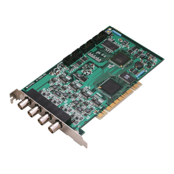
- Page 1 PC-HELPER 10MSPS 12-bit Analog Input Board for PCI AI-1204Z-PCI User’s Guide CONTEC CO.,LTD.
- Page 2 Check Your Package Thank you for purchasing the CONTEC product. The product consists of the items listed below. Check, with the following list, that your package is complete. If you discover damaged or missing items, contact your retailer. Product Configuration List - Board [AI-1204Z-PCI] …1...
-
Page 3: Copyright
No part of this document may be copied or reproduced in any form by any means without prior written consent of CONTEC CO., LTD. CONTEC CO., LTD. makes no commitment to update or keep current the information contained in this document. The information in this document is subject to change without notice. -
Page 4: Table Of Contents
Parts of the Board and Factory Defaults ..................14 Setting the Board ID ........................15 Switch Setting for Termination Resistor..................15 Plugging the Board ........................16 Step 3 Installing the Hardware ......................17 Turning on the PC .......................... 17 AI-1204Z-PCI... - Page 5 Digital Input Function ...........................51 Digital Output Function.........................52 Event Controller Function ........................53 ABOUT SOFTWARE CD-ROM Directory Structure.......................55 About Software for Windows .......................56 Accessing the Help File........................56 Using Sample Programs .........................57 Usage of Utility Program .......................59 Uninstalling the Driver Libraries....................62 ABOUT HARDWARE Hardware specification..........................65 AI-1204Z-PCI...
- Page 6 Block Diagram ............................67 Timing of Sampling Control Signals....................68 Control Signal Timings for Analog Input ..................68 About Calibration..........................70 AI-1204Z-PCI...
- Page 7 AI-1204Z-PCI...
-
Page 8: Before Using The Product
A synchronization control connector is provided for synchronized control of up to 16 boards. This means the number of channels can be increased simply by adding boards. It is also easy to synchronize operation with other CONTEC boards that have a synchronization control connector. AI-1204Z-PCI... - Page 9 - Windows compatible driver libraries are attached. Using the attached driver library API-PAC(W32) makes it possible to create applications of Window. In addition, a diagnostic program by which the operations of hardware can be checked is provided. AI-1204Z-PCI...
-
Page 10: Support Software
Visual Basic, Visual C++, Visual C#, Delphi, C++ Builder You can download the updated version from the CONTEC’s Web site (http://www.contec.com/apipac/). For more details on the supported OS, applicable language and new information, please visit the CONTEC’s Web site. Cable & Connector (Option) <... -
Page 11: Customer Support
You can download updated driver software and differential files as well as sample programs available in several languages. Note! For product information Contact your retailer if you have any technical question about a CONTEC product or need its price, delivery time, or estimate information. Limited Three-Years Warranty CONTEC products are warranted by CONTEC CO., LTD. -
Page 12: Safety Precautions
WARNING indicates a potentially hazardous situation which, if not avoided, could WARNING result in death or serious injury. CAUTION indicates a potentially hazardous situation which, if not avoided, may CAUTION result in minor or moderate injury or in property damage. AI-1204Z-PCI... -
Page 13: Handling Precautions
Even when using the product continuously, be sure to read the manual and understand the contents. Do not modify the product. CONTEC will bear no responsibility for any problems, etc., resulting from modifying this product. Regardless of the foregoing statements, CONTEC is not liable for any damages whatsoever (including damages for loss of business profits) arising out of the use or inability to use this CONTEC product or the information contained herein. -
Page 14: Environment
(3) Store the package at room temperature at a place free from direct sunlight, moisture, shock, vibration, magnetism, and static electricity. Disposal When disposing of the product, follow the disposal procedures stipulated under the relevant laws and municipal ordinances. AI-1204Z-PCI... - Page 15 1. Before Using the Product AI-1204Z-PCI...
-
Page 16: Setup
For setting up software other than API-PAC(W32), refer to the manual for that software. See also the following parts of this manual as required. This chapter Step 2 Setting the Hardware This chapter Step 3 Installing the Hardware Chapter 3 External Connection Chapter 6 About Hardware AI-1204Z-PCI... -
Page 17: Using The Board Under An Os Other Than Windows
2. Setup Using the Board under an OS Other than Windows For using the board under Linux, see the following parts of this manual. This chapter Step 2 Setting the Hardware Chapter 3 External Connection Chapter 6 About Hardware AI-1204Z-PCI... -
Page 18: Step 1 Installing The Software
API-AIO(WDM) is a new driver to perform analog input and output under Windows. It was developed aiming at "more easily use and more convenient" "more high performance" corresponding to the product version of API-AIO(98/PC) so far. Please use the API-AIO(WDM) with this board. API-AIO(98/PC) is not supported. AI-1204Z-PCI... -
Page 19: Starting The Install Program
If the panel does not appear, run (CD-ROM drive letter):\AUTORUN.exe. (3) Click on the [Install Development or Execution Environment] button. CAUTION Before installing the software in Windows 7, Vista, XP, Server 2003, or 2000, log in as a user with administrator privileges. AI-1204Z-PCI... - Page 20 Clicking on the [API-AIO] button under the “Detail” displays detailed information about API-AIO(WDM) and API-AIO(98/PC). Run the installation (1) Complete the installation by following the instructions on the screen. (2) The Readme file appears when the installation is complete. You have now finished installing the software. AI-1204Z-PCI...
-
Page 21: Step 2 Setting The Hardware
Parts of the Board and Factory Defaults Figure 2.1. shows the names of major parts on the board. Note that the switches and jumpers setting shown below is the factory default. Board ID Setting switch AI-1204Z-PCI BOARD ID (SW5) BOARD ID... -
Page 22: Setting The Board Id
Termination resistor setting If you want to set a termination resistor, set the switch corresponding to the desired channel to the connector side. Termination resistor 50Ω setting Termination resistor 50Ω setting [Enabled] [Disabled] <factory default> Figure 2.3. Termination resistor setting AI-1204Z-PCI... -
Page 23: Plugging The Board
Make sure that your PC or expansion unit can supply ample power to all the boards installed. Insufficiently energized boards could malfunction, overheat, or cause a failure. Power supply from the PCI bus slot at +5V is required. AI-1204Z-PCI... -
Page 24: Step 3 Installing The Hardware
(1) When the " Found New Hardware Wizard" opens, select "Install the software automatically [Recommended]" and then click the "Next" button. The wizard may not appear for some OS versions and instead the installation will start automatically. In this case, proceed to the software initial setup step. AI-1204Z-PCI... - Page 25 If using Windows 98 or Windows Me, specify the folder that contains the setup information (INF) file from the CD-ROM. Source folder The setup information (INF) file is contained in the following folder on the bundled CD-ROM. \INF\WDM\AIO \INF\WDM\AIO You have now finished installing the software. AI-1204Z-PCI...
-
Page 26: Step 4 Initializing The Software
- AI-1204Z-PCI (2) The installed hardware appears under the CONTEC Devices node. Open the CONTEC Devices node and select the device you want to setup (the device name should appear highlighted). Click [Properties]. AI-1204Z-PCI... - Page 27 - AI-1204Z-PCI The initial device name that appears is a default value. You can use this default name if you wish. Make sure that you do not use the same name for more than one device.
-
Page 28: Step 5 Checking Operations With The Diagnosis Program
I/O status, and interrupt status. Check Method Connect an external signal source to check the analog input data. The diagrams below show examples of using channel 0 on the AI-1204Z-PCI. For details on the connections, see Chapter 3 “External Connection”. < Analog input >... -
Page 29: Using The Diagnosis Program For Use Of Api-Aio(Wdm)
Click the [Diagnosis] button on the device property page to start the diagnosis program. * The name of the board you have just added is displayed. - AI-1204Z-PCI * The name of the board you have just added is displayed. - Page 30 Clicking [Diagnosis Report] prompts you to specify where to save the report text file. * The name of the board you have just added is displayed. - AI-1204Z-PCI AI-1204Z-PCI...
- Page 31 2. Setup (2) The diagnosis report contains the following data. Version of OS Device Information File Information Initialization, interrupts, current input or output state for each channel AI-1204Z-PCI...
-
Page 32: Setup Troubleshooting
Check the return values of the API functions. Refer to the source code for the sample programs. The OS won’t normally get started or detect the device. Refer to the "Troubleshooting" section of API-AIO(WDM) HELP. If your problem cannot be resolved Contact your retailer. AI-1204Z-PCI... - Page 33 2. Setup AI-1204Z-PCI...
-
Page 34: External Connection
* Please refer to chapter 1 for more information on the supported cable and accessories. Figure 3.1. Interface Connector Shape * Please refer to chapter 1 for more information on the supported cable and accessories. Figure 3.2. Examples of Connecting Options AI-1204Z-PCI... -
Page 35: Connector Pin Assignment
N.C. No connection to this pin. Figure 3.4. Pin Assignment of CN2 CAUTION Do not connect any of the outputs to the analog or digital ground. Neither connect outputs to each other. Doing either can result in a fault. AI-1204Z-PCI... - Page 36 Digital Input 3 5 13 External Start Trigger Input External Stop 14 External Sampling Trigger Input Clock Input AI Status Output 7 15 Digital Ground Reserved 8 Figure 3.6. 15 pins D-SUB of optional cable -- Connector Pin Assignment AI-1204Z-PCI...
-
Page 37: Analog Input Signal Connection
An input pin may fail to obtain input data normally when the signal source connected to the pin has high output impedance. If this is the case, change the signal source to one with lower output impedance or insert a high-speed amplifier buffer between the signal source and the analog input board to reduce the effect. AI-1204Z-PCI... -
Page 38: Digital I/O Signals And Control Signals Connection
If connected to each output, a pull-up resistor must be about 10 kΩ to pull up with a 3.3V power source. Each input accepts 5V TTL signals. Reference For the operation timings for control signal input, see ”Timing of External Control Signals” in Chapter 6 “Hardware”. AI-1204Z-PCI... -
Page 39: Synchronization Control Connectors
(5) Start in order of slave to master boards. CAUTION When clock signals are assigned to the synchronization control connector, the maximum clock frequency is restricted to 5MHz. When signals are assigned to the synchronization control connector, a delay of approximately 100nsec occurs at the slave board. AI-1204Z-PCI... -
Page 40: Connecting The Sc Connectors (Cn3, Cn4)
Connect CN3 with a smaller ID number to CN4 with a greater ID number with the cable. You should only use the cable that came with the board. ID = 0 ID = 1 ID = 2 Figure 3.10. Connecting Cables AI-1204Z-PCI... - Page 41 3. External Connection AI-1204Z-PCI...
-
Page 42: Functions
Stop Condition Channel Delay Channel Event conversion order Range Data transfer method Memory format 2. Starting / stopping operation Start Stop 3. Monitoring the Status and Acquiring Data Status Sampling Transfer Data acquisition Conversion data 4. Reset Status Memory AI-1204Z-PCI... -
Page 43: Setting The Conversion Conditions
If the device has a resolution of 16bit, it is 10÷65536 ≈ 0.153mV instead. Analog voltage before conversion Low-resolution board High-resolution board AI-1204Z-PCI : The resolution is 12bit. Input Mode ”Input Mode” indicates the method of connecting analog input signals. - Page 44 0 as shown below. If you wish, you can specify a different channel conversion order. Range ”Range” means the range of voltages at which analog input can be performed. AI-1204Z-PCI : The input range is set by software. AI-1204Z-PCI...
- Page 45 When conversion starts, conversion data is transferred via the driver directly to the application memory. Whether or not to overwrite memory can be specified in user buffer mode. Device buffer mode User buffer mode AI-1204Z-PCI...
- Page 46 The ring memory is used to obtain data where conversion has stopped due to some event, usually without obtaining data in the normal state. Writing of data The number of times of sampling AI-1204Z-PCI...
- Page 47 The edge of the digital signal input from an external device is used for the sampling clock. event controller output A specified output of the event controller is used as the sampling clock. Refer to the explanation of the event controller functions or to the driver help for details about the event controller. AI-1204Z-PCI...
- Page 48 Input data items are stored to memory, starting with those at solid dots. If you set the level comparison directions to both directions, the start condition is satisfied when the analog signal passes the level both in the rising and falling directions. AI-1204Z-PCI...
- Page 49 This product starts waiting for an external control signal as soon as the operation start command is output. Sampling and data transfer to memory start when the specified event controller output is received. Refer to the explanation of the event controller functions or to the driver help for details about the event controller. AI-1204Z-PCI...
- Page 50 Input data items are stored to memory, ending until those at solid dots If you set the level comparison directions to both directions, the start condition is satisfied when the analog signal passes the level both in the rising and falling directions. AI-1204Z-PCI...
- Page 51 Sampling continues indefinitely in this mode. Sampling only stops in response to a software command or an error. Event controller output Sampling stops when the specified event controller output is received. Refer to the explanation of the event controller functions or to the driver help for details about the event controller. AI-1204Z-PCI...
-
Page 52: Starting/Stopping Operation
AD conversion error event This event occurs when conversion stops due to an AD conversion error. 2. Starting/Stopping Operation Sampling is started by the software command. Once started, sampling can be stopped by the software command at any timing. AI-1204Z-PCI... -
Page 53: Monitoring The Status And Acquiring Data
This command can only be used in device buffer mode. Transfer The number of sampled items of input data stored in memory can be obtained by the software command. This command can only be used in user buffer mode. AI-1204Z-PCI... - Page 54 The FIFO memory deletes data once that data is acquired. Data acquired Free memory Conversion data space for user memory Conversion data Free memory space AI-1204Z-PCI...
- Page 55 Each packet contains two DA conversion data values in binary format. In the above example, the lower two bytes of the packet contain the channel 0 data and the upper two bytes contain the channel 1 data. When using 2channels, each packet (each data transfer) contains the data for one sampling. AI-1204Z-PCI...
- Page 56 32769 2048 32768 -0.005V 2047 -0.00030V 32767 -10.000V -10.000V Ex.: When input data 3072 is input at a resolution of 12bit in the ± 10-volt range Voltage = 3072 x (10 - (-10)) ÷ 4096 + (-10) = 5.0 AI-1204Z-PCI...
-
Page 57: Reset
This command resets the following memory related states. Resets the conversion data in memory. Resets the sampling count to 0 when a stop trigger is input. Resets the buffer overflow status. Resets the status information for the specified data save count. AI-1204Z-PCI... -
Page 58: Digital Input Function
Byte data = 5(5H) bit3 bit2 bit1 bit0 0(OFF) 1(ON) 0(OFF) 1(ON) Digital filter A digital filter can be used on the input bits. The filter time can be set to "don't use", 50ns, 1μs, 10μs, or 100μs by software. AI-1204Z-PCI... -
Page 59: Digital Output Function
0 and 15. Ex. Output of bit 3 (ON), bit 2 (OFF), bit 1 (ON),and bit 0 (OFF) Byte data = 10(AH) bit3 bit2 bit1 bit0 1(ON) 0(OFF) 1(ON) 0(OFF) AI-1204Z-PCI... -
Page 60: Event Controller Function
Setting up the event controller (Device 1) Setup the event controller to connect the software start signal to the synchronization connector for output to device 2.The signal destination is synchronization bus master signal 1 and the signal source is the analog input software start signal. AI-1204Z-PCI... - Page 61 The signal destination is the sampling clock for analog input and the signal source is synchronization bus slave signal 2. Start conversion In this example, conversion is started first on device 2. When analog input starts on device 1, analog input starts simultaneously on device 2. AI-1204Z-PCI...
-
Page 62: About Software
| ––INF Each INF file for OS |––WDM |––Win2000 |––Win95 | ––Readme Readme file for each driver | ––Release Driver file on each API-TOOL |––API_NT (For creation of a user-specific install program) |––API_W95 | ––UsersGuide Hardware User's Guide (PDF files) AI-1204Z-PCI... -
Page 63: About Software For Windows
Reference”, “Sample Programs”, and “FAQs”. Use them for program development and troubleshooting. Accessing the Help File (1) Click on the [Start] button on the Windows taskbar. (2) From the Start Menu, select “Programs” – “CONTEC API-PAC(W32)” – “AIOWDM” – “API-AIO(WDM) HELP” to display help information. AI-1204Z-PCI... -
Page 64: Using Sample Programs
The sample programs are stored in \Program Files\CONTEC\API-PAC(W32)\AIOWDM\Samples. Running a Sample Program (1) Click on the [Start] button on the Windows taskbar. (2) From the Start Menu, select “Programs” - “CONTEC API-PAC(W32)” - “AIOWDM” - “SAMPLE…”. (3) A sample program is invoked. - Page 65 Perform analog input for a specified duration using a user buffer - AiUser2 Perform analog input indefinitely using a user buffer Digital input/output - DioBit Perform digital I/O using bit values - DioByte Perform digital I/O using port values Others - Convert Data conversion - Multi1 Synchronized analog I/O AI-1204Z-PCI...
-
Page 66: Usage Of Utility Program
* The name of the board you have just added is displayed. - AI-1204Z-PCI Procedure (1) Chose the measure device from device list. (2) Click the button written with the function name to measure the execution speed of the function. - Page 67 Since the notification of a sampling clock error event is sent, please make use of it for the conversion spec measurement under various conversion conditions. * The name of the board you have just added is displayed. - AI-1204Z-PCI AI-1204Z-PCI...
- Page 68 The cycle of the clock is too fast when converting it at the external clock. Moreover, the cause by noise etc. is also concerned. Buffer overflow : The memory overflows since the conversion speed is too fast compared with the one at which data is inputted. (4) Click the “stop” button, and measurement stops. AI-1204Z-PCI...
-
Page 69: Uninstalling The Driver Libraries
[Device Manager] tab. (You can also open Device Manager by right clicking on My Computer and selecting Properties.) 2. All of the hardware that uses the API-TOOL(WDM) driver is registered under the CONTEC Devices tree. Open the device tree, select the hardware to uninstall, and then right-click the hardware. - Page 70 < Uninstall the device driver > Use [My Computer] - [Control Panel] - [Add and Remove Applications] to uninstall the device driver. Select [Windows driver package - CONTEC (****)] and then click [Change/Remove]. * "***" contains the driver category name (caio, ccnt, cdio, csmc, etc.).
- Page 71 < Uninstall the device driver > Use [My Computer] - [Control Panel] - [Add and Remove Applications] to uninstall the device driver. Select [CONTEC API-***(WDM) driver] and then click [Add and Remove Applications]. * "***" contains the driver category name (AIO, CNT, DIO, SMC, etc.).
-
Page 72: About Hardware
*2: The rated precision may not be achieved depending on the cable used. *3: The non-linearity error means an error of approximately 0.1% occurs over the maximum range at 0 ° C and 50 ° C ambient temperature. *4: A R6161[ADVANTEST] voltage generator was used for measurements. AI-1204Z-PCI... - Page 73 *5: This product requires +5V power supply from expansion slots (it does not operate in the environment of only +3.3V power supply). Board Dimensions 176.41(L) [mm] The standard outside dimension (L) is the distance from the end of the board to the outer surface of the slot cover. AI-1204Z-PCI...
-
Page 74: Block Diagram
Figure 6.1 is a circuit block diagram of this product. 4 Digital Inputs / 4 Digital Outputs 4 single-end External Trigger Inputs / Outputs Analog Inputs Amplifier Amplifier Amplifier Amplifier Converter Converter Converter Converter FPGA DRAM PCI Bus Figure 6.1. Block Diagram AI-1204Z-PCI... -
Page 75: Timing Of Sampling Control Signals
Control Signal Timings for Analog Input AI-1204Z-PCI is unrelated with the sampling clock, it is always sampled in each 100nsec. In a word, the conversion results from the A/D convertor are stored in an internal register once, the values are updated in each 100nsec. - Page 76 Hold time of sampling stop (Rising edge) nsec Set up time of sampling stop (Falling edge) nsec Hold time of sampling stop (Falling edge) nsec CAUTION All the model values are shown at the time of Table 6.2. AI-1204Z-PCI...
-
Page 77: About Calibration
Click the [Calibration] button on the property page for the device to start the calibration program. * The name of the board you have just added is displayed. - AI-1204Z-PCI Proceed with connecting the calibration equipment and performing the calibration in accordance with the instructions displayed by the calibration program. Analog input calibration Analog input calibration requires a reference voltage generator. - Page 78 3-9-31, Himesato, Nishiyodogawa-ku, Osaka 555-0025, Japan Japanese http://www.contec.co.jp/ English http://www.contec.com/ Chinese http://www.contec.com.cn/ No part of this document may be copied or reproduced in any form by any means without prior written consent of CONTEC CO., LTD. [12112009] [12112007] Management No. A-51-407 [12112009_rev5] Parts No.
Need help?
Do you have a question about the AI-1204Z-PCI and is the answer not in the manual?
Questions and answers