Table of Contents
Advertisement
RuiDa Technology Co., Ltd
Addr:
3th
floor,Technology
Avenue,Nanshan
Province,P.R.China
Tel:
0755--26066687
Fax:
0755--26982287
E-mail:
sales@rd-acs.com
Web:
www.rd-acs.com
SHENZHEN RUIDA TECHNOLOGY
User's Manual of RDC644XG Control System
Read this manual before operation
The content include of electric connections and operating steps
Read the manual to operate the systems
RDC644XG
Building,NO.,1067
District,Shenzhen
city,Guangdong
Control System
Nanhai
https://www.ruidacontroller.com
Advertisement
Table of Contents

Subscribe to Our Youtube Channel
Related Manuals for RuiDa RDC644XG


Summary of Contents for RuiDa RDC644XG
- Page 1 User’s Manual of RDC644XG Control System Read this manual before operation The content include of electric connections and operating steps Read the manual to operate the systems RDC644XG Control System RuiDa Technology Co., Ltd Addr: floor,Technology Building,NO.,1067 Nanhai...
- Page 2 All rights reserved.You may not reproduce, transmit, store in a retrieval system or adapt thispublication, in any form or by any means, without the prior written permissionof RuiDa, except as allowed under applicable copyright laws. We have identifiedwords that we consider as trademarks. Neither the presence or absence oftrademark identifications affects the legal status of any trademarks.
- Page 3 User’s Manual of RDC644XG Control System CERTIFICATION DECLARATION The product has been certified by the CE (Commutate European) safety certification. It has passed the corresponding conformity assessment procedure and the manufacturer's declaration of conformity, in accordance with the relevant EU directive.
- Page 4 User’s Manual of RDC644XG Control System SAFETY INFORMATION When using this system, please make sure the operation is correct and the usage is safe. Some signs or text will be used to remind you to pay attention to the dangerous matters and some important information.
- Page 5 After receiving the product, please check whether the outer package is intact, check whether the product is complete after unpacking and whether all parts are intact. If any damage is found, please contact ruida immediately. Remove all cargo from package and keep packing material and wiring parts. Please take care of the safety of the goods when unpacking them.After taking out the goods, please...
-
Page 6: Table Of Contents
User’s Manual of RDC644XG Control System Contents 1.1 B ............................2 RIEFING 1.2 D ....................2 ESCRIPTION OF ONTROLLER ODEL ..................2 1.3 C OMPARISON OF ONTROLLER ERFORMANCE Section 2 Installation Size......................5 2.1 I ....................6 NSTALLATION IZE OF OARD ..........................7 2.2 S... - Page 7 User’s Manual of RDC644XG Control System 8.2.4 Set the layer parameters.....................35 ............................. 36 8.3 Z/U K 8.3.1 Z move..........................36 8.3.2 U move........................... 36 8.3.3 Axis reset........................36 8.3.4 Manual set+........................37 8.3.5 Laser set+........................38 8.3.6 Origin set+........................38 8.3.7 Set Fact Para........................ 40 8.3.8 Def Fact Para........................
- Page 8 User’s Manual of RDC644XG Control System Section 1 Overview CONTENTS: Briefing Description of Controller Model Comparison of Controller Performance SHENZHEN RUIDA TECHNOLOGY...
-
Page 9: Briefing
User’s Manual of RDC644XG Control System 1.1 Briefing RDC644XG system is a new generation system for control of laser engraving and cutting, which is developed by RD Co., Ltd. In addition to high hardware stability, high voltage or static electricity rejection, and friendly 3.5’’... - Page 10 User’s Manual of RDC644XG Control System Compatibility Feature Support Support Support Support all USB disks disks with disks with different disks with different with different capacities small capacity capacities capacities Capacity Memor 256M 256M 128M y Feature Fault Common Capable of checking...
- Page 11 User’s Manual of RDC644XG Control System Z-axle -axle Linkage Feature Feeding Single Single/double Single/double Single/double direction Feature direction direction for option direction for option for option Power-on Fixed Configurable Configurable for each Configurable for each Resetting each axes axes axes...
-
Page 12: Section 2 Installation Size
User’s Manual of RDC644XG Control System Section 2 Installation Size CONTENTS: Installation Size of MainBoard Size of Panel SHENZHEN RUIDA TECHNOLOGY... -
Page 13: Installation Size Of Mainboard
User’s Manual of RDC644XG Control System 2.1 Installation Size of MainBoard The unit of all sizes is millimeter (mm) and the size accurate to 0.1mm (the four holes are symmetrical) Figure 2.1-1 SHENZHEN RUIDA TECHNOLOGY... -
Page 14: Size Of Panel
User’s Manual of RDC644XG Control System 2.2 Size of Panel The unit of all sizes is millimeter (mm) and the size accurate to 0.1mm. Figure 2.2-1 SHENZHEN RUIDA TECHNOLOGY... -
Page 15: Section3 Object Pictures And Interfaces
User’s Manual of RDC644XG Control System Section3 Object Pictures and Interfaces CONTENTS: Object Pictures of MainBoard Object Pictures of Panel Electric connection Lamp instruction SHENZHEN RUIDA TECHNOLOGY... -
Page 16: Object Pictures Of Mainboard
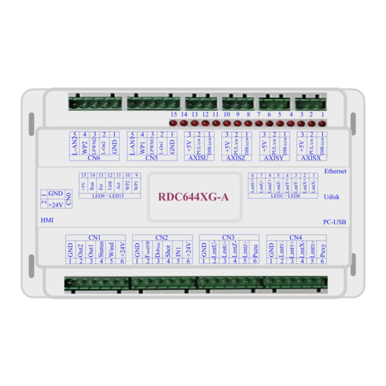
User’s Manual of RDC644XG Control System 3.1 Object Pictures of MainBoard For more detailed pin description, see the Chapter 4: Description of Interface Signal for MainBoard. Figure: 3.1-1 Object Picture of MainBoard SHENZHEN RUIDA TECHNOLOGY... -
Page 17: Object Pictures Of Panel
User’s Manual of RDC644XG Control System 3.2 Object Pictures of Panel Figure: 3.2-1 Object Picture of Panel SHENZHEN RUIDA TECHNOLOGY... -
Page 18: Electric Connection
User’s Manual of RDC644XG Control System 3.3 Electric connection Figure 3.3-1 electric connection SHENZHEN RUIDA TECHNOLOGY... -
Page 19: Lamp Instruction
User’s Manual of RDC644XG Control System 3.4 Lamp instruction RDC6442G have fifteen red lamps: LED NUMBER NAME SENSE LED1 LmtX- negative limit indicator LED2 LmtX+ positive limit LED3 LmtY- negative limit LED4 LmtY+ positive limit LED5 LmtZ- negative limit LED6... -
Page 20: Section 4 Description Of Interface Signal For Mainboard
User’s Manual of RDC644XG Control System Section 4 Description of Interface Signal for MainBoard CONTENTS: Interface of Main Power Source CN0 Panel Signal-Cable Interface HMI Udisk Interface PC-USB Interface Ethernet Interface General Output Port CN1 General Input Port CN2 4-axle Spacing Input Interface CN3/CN4... -
Page 21: Interface Of Main Power Source Cn0
User’s Manual of RDC644XG Control System 4.1 Interface of Main Power Source CN0 Symbols Definitions 24V power ground (input) +24V 24V power positive (input) This control system employs single 24 power supply. For a certain margin, it is suggested to select 24V/2A power. Besides, this system is... -
Page 22: General Output Port Cn1
User’s Manual of RDC644XG Control System 4.6 General Output Port CN1 Definition of general output port Symbols Definitions Power ground (output) Out2 General output, with the function reserved. Out1 General output, with the function reserved. Status General output for the signal port of running status. If this port is externally connected with the relay, the relay coil is broken over when it works;... -
Page 23: 4-Axle Spacing Input Interface Cn3/Cn4
User’s Manual of RDC644XG Control System second stepping-down of the pedal will be considered invalid by the mainboard. DrProc Input from protective port. If the machine needs to be protected in the special state (such as door open protection), the protective signal can be inputted from this pin. This pin can be enabled and prohibited. -
Page 24: X/Y/Z/Uaxle Motor Driver Interface Axis_X~Axis_U
User’s Manual of RDC644XG Control System 4.9 X/Y/Z/U axle Motor Driver Interface AXIS_X~AXIS_U The interfaces of the above four motion axles are the same. The AXIS-X interface is exampled. Symbols Definitions (OC output) Directional signal Pulse signal (OC output) 5V Power positive (output) The polarity of directional signal for driver pulse signal can be set. - Page 25 User’s Manual of RDC644XG Control System 2. When the laser is a glass tube, this pin will be connected with the laser power PWM end and used to control the power of the laser. The input port of water protector for the first laser power source.
- Page 26 User’s Manual of RDC644XG Control System SHENZHEN RUIDA TECHNOLOGY...
-
Page 27: Section5 Examples Of Laser Power Interface
User’s Manual of RDC644XG Control System Section5 Examples of Laser Power Interface CONTENTS: Brief Examples of Glass tube Laser Power Examples of RF-Laser SHENZHEN RUIDA TECHNOLOGY... -
Page 28: Brief
User’s Manual of RDC644XG Control System 5.1 Brief This control system has two independent and adjustable digital laser power control interfaces, which can be used to control glass tube laser power and RF-laser. Please correctly select the laser type in the factory parameters, or, the laser control is incorrect. -
Page 29: Examples Of Glass Tube Laser Power
User’s Manual of RDC644XG Control System 5.2 Examples of Glass tube Laser Power SHENZHEN RUIDA TECHNOLOGY... -
Page 30: Examples Of Rf-Laser
User’s Manual of RDC644XG Control System 5.3 Examples of RF-Laser SHENZHEN RUIDA TECHNOLOGY... -
Page 31: Section6 Examples Of Driver Interface For Step-Servo Motor
User’s Manual of RDC644XG Control System Section6 Examples of Driver Interface Step-servo Motor CONTENTS: Brief Examples of Motor Driver Connection SHENZHEN RUIDA TECHNOLOGY... -
Page 32: Brief
Figure 6.1-1 and 6.1-2. RDC644XG Controller has four groups of 3-wires motion driver interface, each interface has one direction signal, one pulse signal, and one 5V positive output, the direction signal and the pulse signal are all OC output. -
Page 33: Examples Of Motor Driver Connection
User’s Manual of RDC644XG Control System 6.2 Examples of Motor Driver Connection SHENZHEN RUIDA TECHNOLOGY... -
Page 34: Section7 Examples Of Io-Port Wiring
User’s Manual of RDC644XG Control System Section7 Examples of IO-port Wiring CONTENTS: Input Output SHENZHEN RUIDA TECHNOLOGY... -
Page 35: Input
User’s Manual of RDC644XG Control System 7.1 Input The two water protection inputs are 24V logic level; all other inputs are compatible with 5V/12V/24V logic level. Input connection shown as below Figure 7.1-1 example of input SHENZHEN RUIDA TECHNOLOGY... -
Page 36: Output
User’s Manual of RDC644XG Control System 7.2 Output All outputs are isolated through the optocoupler, and 500mA current for each, OC gate output, each can directly drive the 6V/24V relay, led lamp, buzzer etc. Output connection shown as below Figure 7.2-1 example of output... -
Page 37: Section8 Operating Instruction Of Panel
User’s Manual of RDC644XG Control System Section8 Operating Instruction of Panel CONTENTS: Introduction to the Panel and Keys Introduction to the Main Interface Z/U Key File Key Introduction to some alarm info SHENZHEN RUIDA TECHNOLOGY... -
Page 38: Introduction To The Panel And Keys
User’s Manual of RDC644XG Control System 8.1 Introduction to the Panel and Keys 8.1.1 The whole panel 8.1.2 Introduction to the Keys Reset :Reset the whole system; :Set the relative origin; Origin :Let the Laser to splash; ... -
Page 39: Introduction To The Main Interface
User’s Manual of RDC644XG Control System Max. :Set the max laser power of the current running layer, or set the power of Power “Laser” Key; Min. :Set the min laser power of the current running layer; Power Start/ :To start or pause the work;... - Page 40 User’s Manual of RDC644XG Control System Figure 8.2-1 Graph Display Area: To display the whole file’s track, and display the running track. Running parameters: To display the running file’s file number, speed, max power etc.; Coordinate: To display the current coordinate of X,Y and Z axes ...
-
Page 41: Speed Key
User’s Manual of RDC644XG Control System 8.2.2 Speed key Push the “Speed” key when the screen is on the main interface, it will show as below: Figure 8.2-2 Push the “X+/-“ Keys to move the cursor in the numeral area, and push the “Y+/-” keys to change the value, then push the “Enter”... -
Page 42: Set The Layer Parameters
User’s Manual of RDC644XG Control System Figure 8.2-4 When “Z/U” key is pushed, the green block can move up and down to denote the changing item, then “Y+/-” keys and “X+/-” keys can be used to change the value. 8.2.4 Set the layer parameters After selecting a file to preview on the main interface, user can push “Enter”... -
Page 43: Z/U Key
User’s Manual of RDC644XG Control System User can push “Z/U” Keys to move the green block on the intent parameter, then he could change the parameter if needed. “OK” to validate the change, and “Esc” to invalidate the change. 8.3 Z/U Key The Z/U key can be pressed when the system is idle or the work is finished. -
Page 44: Manual Set
User’s Manual of RDC644XG Control System Figure 8.3-2 Push the “Y+/-“ Keys to move the cursor to one of the entry, then push “Enter” key to restart the selected axis, the screen will show some information when resetting. 8.3.4 Manual set+ When the green block is on this item, push the “Enter”... -
Page 45: Laser Set
User’s Manual of RDC644XG Control System corresponding axes will move a fixed length, unless the scope is overstepped. 8.3.5 Laser set+ When the green block is on this item, push the “Enter” key to show as below: Figure 8.3-4 Push “Z/U” key to move the green block, and when the green block is on the “Mode” item, push “X+-“... - Page 46 User’s Manual of RDC644XG Control System Figure 8.3-5 Push “Z/U” key to move the green block to the anticipant item, and when the green block is on “enable” items, push “Enter” key to enable or disable the item, when enabled, the small diamonds is green, and when disabled, the small diamonds is grey.
-
Page 47: Set Fact Para
User’s Manual of RDC644XG Control System origin logic. Next origin can be modified to any one of origin 1~4, so as to control the start location of next work (the premise is that the origin is enabled), but it can’t be modified to origin 0. -
Page 48: Def Fact Para
User’s Manual of RDC644XG Control System 8.3.8 Def Fact Para After the “Def Fact Para” is selected and the Enter key pressed, the “Successful Recovery” dialog box will pop up to prompt that all manufacturer parameters and user parameters are recovered successfully. -
Page 49: Diagnoses
User’s Manual of RDC644XG Control System Figure 8.3-8 Push “Z/U” key to move the changing item, then push “X+/-” keys and “Y+/-” keys to change the value, when all the IP value and the Gateway value are changed, push “Enter”... -
Page 50: Screen Origin
User’s Manual of RDC644XG Control System 8.3.13 Screen Origin If the “Screen Origin” item is pressed, the system will show as below: Figure 8.3-10 There are four entries to be selected: Top Left, Top Right, Bottom Left and Bottom Right. When one is selected, the previewed graph on the screen would be enantiomorphous based on X or Y direction. - Page 51 User’s Manual of RDC644XG Control System Figure 8.4-1 When showing this menu, the system would read the memory file firstly, the file name and the work times would be listed in the area, and the selected file is previewed in the bottom right area.
-
Page 52: U Disk File
User’s Manual of RDC644XG Control System Figure 8.4-2 Current work time: To forecast the running time of the current file(the current file No. is showed on the main interface), and the time is accurate to 1ms. Clear all count: To clear the running times of every file in the memory ... -
Page 53: Introduction To Some Alarm Info
User’s Manual of RDC644XG Control System Figure 8.4-3 Read Udisk: read the file list in the Udisk; Copy to memory: copy the target Udisk file to the memory; Delete: delete the selected Udisk file; This system supports such file formats of Udisk as FAT32 and FAT16, but it can identify them when the files are put under the root directory of Udisk. - Page 54 User’s Manual of RDC644XG Control System Figure 8.5-1 Push “Enter” key or “Esc” key, the system will execute some relative steps. SHENZHEN RUIDA TECHNOLOGY...
-
Page 55: Section9 Manufacturer/User Parameters Explanation
User’s Manual of RDC644XG Control System Section9 Manufacturer/User Parameters Explanation CONTENTS: Manufacturer parameters User parameters SHENZHEN RUIDA TECHNOLOGY... -
Page 56: Manufacturer Parameters
User’s Manual of RDC644XG Control System 9.1 Manufacturer parameters (1)Motor parameters X/Y/Z/U axle parameters Direction Polarity: Modification of direction polarity can move the motor to the opposite direction. The modification purpose can move this axle to the origin on resetting. If this axle moves far from the origin on resetting, it means the direction polarity of this axle is wrong in setting and should be modified. - Page 57 User’s Manual of RDC644XG Control System axle can bear. This parameter has something to do with the driving force of motor, the inertia of motion axle and its drive ratio. For example, the typical value is 200~500mm/s. Maximum Acceleration: it means the maximum acceleration of the motion axle in accelerated or decelerated motion.
- Page 58 User’s Manual of RDC644XG Control System to pre-generate PWM, then set the Pre-generation Frequency and the Pre-generation pulse scale. Water Protector Enabled: When the water protector is enabled, the mainboard will detect the input port of water protector. If this port is of low level, it will be deemed normal;...
-
Page 59: User Parameters
User’s Manual of RDC644XG Control System After the configuration parameters in the manufacturer parameters, such as directional polarity, control mode, laser type and laser PWM Prompt frequency, are modified, the system should be reset. Such a modification can function upon the resetting of the system. - Page 60 User’s Manual of RDC644XG Control System (2)Scanning parameters(Only affect scanning arts) X-axle Starting Speed Y-axle Starting Speed X-axle Acceleration Y-axle Acceleration The above four parameters are used to set the starting speed and acceleration of two axles on the scanning. The higher the two speeds are, the quicker the scanning is.
- Page 61 User’s Manual of RDC644XG Control System moving, there can set a value to repay the interval of the two lines graph on Y direction. (4)Reset parameters Reset Speed: it means the speed of X/Y-axle linkage reset to the origin.
- Page 62 User’s Manual of RDC644XG Control System Thank you for your selection of our production! All the copyright of this manual is owned by Ruida technology. Any person or company can not copy upload and send the manual without Ruida’s permission.
- Page 63 SHENZHEN RUIDA TECHNOLOGY...
Need help?
Do you have a question about the RDC644XG and is the answer not in the manual?
Questions and answers