Table of Contents
Advertisement
RDC6563F Standalone Fiber Cutting Control System User Manual V2.0
Standalone Fiber Cutting Control
System User Manual V2.0
SHENZHEN RUIDA TECHNOLOGY CO., LTD
Address : 301A.302B,Technology Building,NO.,1067 Nanhai
Avenue,Nanshan District,Shenzhen city,Guangdong
Province,P.R.China
Tel:
0755--26066687
Fax:
0755--26982287
E-mail: sales@rd-acs.com
Website: www.rd-acs.com
Users should read this manual before using the controller.
This manual contents is the system operation manual
Read this manual carefully to ensure proper electrical connection
SHENZHEN RUIDA TECHNOLOGY CO., LTD
RDC6563F
I
Advertisement
Table of Contents

Subscribe to Our Youtube Channel
Related Manuals for RuiDa RDC6563F


Summary of Contents for RuiDa RDC6563F
- Page 1 RDC6563F Standalone Fiber Cutting Control System User Manual V2.0 Users should read this manual before using the controller. This manual contents is the system operation manual Read this manual carefully to ensure proper electrical connection RDC6563F Standalone Fiber Cutting Control System User Manual V2.0...
- Page 2 Ruida Technology shall not be liable for any direct, indirect, special, incidental or consequential loss or liability arising from the use of this manual or the improper use of this product. Ruida Technology does not assume the following direct or indirect liabilities or losses.
- Page 3 RDC6563F Standalone Fiber Cutting Control System User Manual V2.0 Certification statement CE Certification statement This product has passed the CE (Community European) safety certification, and has passed the corresponding conformity assessment procedures and the manufacturer's declaration of conformity, in line with the relevant EU directives.
- Page 4 RDC6563F Standalone Fiber Cutting Control System User Manual V2.0 Safety information Please make sure that the operation is correct and the method is safe when using the system. Some signs or words will be used to remind you of dangerous matters and some important information.
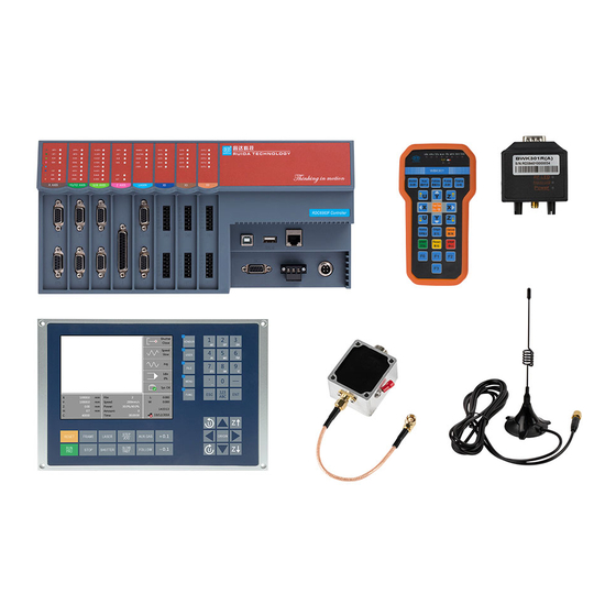
- Page 5 Ruida Technology immediately. If you notice any obvious damage to the device, do not install the device or commission the device. RDC6563F standalone fiber cutting system delivery list is shown in the following: ( As the product is constantly updated, the accessories that may be received are different from this list)...
- Page 6 RDC6563F Standalone Fiber Cutting Control System User Manual V2.0 Sensor cable -16cm- Silver white U-disk-4G Steel rail 350*35*7.5MM Rail mount 3.81MM- Curved insertion socket-black 5.08MM- Curved insertion --3P socket - black - With fixing screws DB15- Welding wire-3 DB15-VGA shell...
-
Page 7: Table Of Contents
RDC6563F Standalone Fiber Cutting Control System User Manual V2.0 Contents Chapter 1 Overview............................. 9 Introduction to standalone fiber cutting control system............10 1.1.1 Functional Description.......................10 RDC6563F main technical parameters.................. 11 1.2.1 RDC6563F main technical parameters................11 1.2.2 Z Axis following system technical parameters.............. 11 Mainboard size chart......................... - Page 8 RDC6563F Standalone Fiber Cutting Control System User Manual V2.0 3.7.4 Screen Origin Settings...................... 61 3.7.5 System Information......................61 3.7.6 Multiple Anchor Point Settings..................62 3.7.7 Parameter Backup......................64 3.7.8 Parameter Recovery......................64 3.7.9 Permission Settings......................64 Functions............................. 65 3.8.1 Axis reset..........................65 3.8.2...
- Page 9 RDC6563F Standalone Fiber Cutting Control System User Manual V2.0 7.1.14 Machine alarm........................94 7.1.15 Frame crossing........................95 7.1.16 Mainboard communication failed..................95 7.1.17 No file........................... 95 Chapter 8 Device Connection....................... 96 USB drive installation........................ 97 8.1.1 USB Automatic installation....................97 USB Device connection......................98 Ethernet device connection......................
-
Page 10: Chapter 1 Overview
RDC6563F Standalone Fiber Cutting Control System User Manual V2.0 Chapter 1 Overview Main contents RDC6563F system introduction RDC6563F Technical parameter introduction Product installation dimension drawing SHENZHEN RUIDA TECHNOLOGY CO., LTD... -
Page 11: Introduction To Standalone Fiber Cutting Control System
RDC6563F Standalone Fiber Cutting Control System User Manual V2.0 1.1 Introduction to standalone fiber cutting control system RDC6563F is a fiber cutting control system independently developed by Ruida Technology. This control system has better hardware stability and better resistance to high voltage and antistatic interference. -
Page 12: Rdc6563F Main Technical Parameters
RDC6563F Standalone Fiber Cutting Control System User Manual V2.0 1.2 RDC6563F main technical parameters 1.2.1 RDC6563F main technical parameters Supports up to 6 axes of high speed motion, and with a maximum pulse frequency of 500 KHz. Each axis supports positive and negative limits, servo alarm input detection and ... -
Page 13: Mainboard Size Chart
RDC6563F Standalone Fiber Cutting Control System User Manual V2.0 1.3 Mainboard size chart RDC6563FMainboard size is shown below: unit:mm Top view Front view SHENZHEN RUIDA TECHNOLOGY CO., LTD... - Page 14 RDC6563F Standalone Fiber Cutting Control System User Manual V2.0 Left view Bottom view SHENZHEN RUIDA TECHNOLOGY CO., LTD...
-
Page 15: Panel Size Chart
RDC6563F Standalone Fiber Cutting Control System User Manual V2.0 1.4 Panel size chart RDC6563F panel size is shown below: unit:mm Front view SHENZHEN RUIDA TECHNOLOGY CO., LTD... - Page 16 RDC6563F Standalone Fiber Cutting Control System User Manual V2.0 Bottom view Right view SHENZHEN RUIDA TECHNOLOGY CO., LTD...
-
Page 17: Amplifier Installation Dimensions
RDC6563F Standalone Fiber Cutting Control System User Manual V2.0 1.5 Amplifier installation Dimensions The amplifier size is shown below: Unit:mm SHENZHEN RUIDA TECHNOLOGY CO., LTD... -
Page 18: Chapter 2 Hardware Wiring Instruction
RDC6563F Standalone Fiber Cutting Control System User Manual V2.0 Chapter 2 Hardware Wiring Instruction Main contents: System wiring diagram Hardware interface description Motor wiring instructions Laser wiring instructions SHENZHEN RUIDA TECHNOLOGY CO., LTD... -
Page 19: System Wiring Diagram
RDC6563F Standalone Fiber Cutting Control System User Manual V2.0 2.1 System wiring diagram The overall wiring diagram of the system as belowing: 2.2 Sensor Amplifier interface Sensor is an amplifier connection interface , this interface is connects one end of the 15-meter cable to the height sensor and the other connects to the amplifier. -
Page 20: Hmi Interface
RDC6563F Standalone Fiber Cutting Control System User Manual V2.0 signal definition Description controller+24V power input, Power supply +24V +24V power input current output capability is greater than 3A — Generally connected to the earth or the External shield shell 2.4 HMI interface HMI is DB9 interface, the manufacturer's special shielded cable to connect mainboard and HMI. -
Page 21: Ethernet Interface
RDC6563F Standalone Fiber Cutting Control System User Manual V2.0 2.7 Ethernet interface Ethernet is an Ethernet communication interface, which is connected to the PC network port through a network cable, enabling 10/100 MHz Ethernet communication between the mainboard and the PC. When set to network cable connection, Select network connection from RDCutist software. - Page 22 RDC6563F Standalone Fiber Cutting Control System User Manual V2.0 Signal definition Description PIN1 controller+5V power output,Current +5V power(output) output capability greater than 500mA PIN2 DIR- DIR- PIN3 DIR+ DIR+ PIN4 PULSE- PULSE- PIN5 PULSE+ PULSE+ PIN6 Servo drive enable signal (output)...
- Page 23 RDC6563F Standalone Fiber Cutting Control System User Manual V2.0 Common anode connection If connects to servo motor, please set servo driver parameters correctly according to the specific model. Panasonic A5 series servo drive wiring instructions Sanyo R series servo drive wiring instructions...
- Page 24 RDC6563F Standalone Fiber Cutting Control System User Manual V2.0 Schneider 23A series servo drive wiring instructions Fuji A5 series servo drive wiring instructions Delta A series servo drive wiring instructions SHENZHEN RUIDA TECHNOLOGY CO., LTD...
-
Page 25: Z Axis Motor Interface
RDC6563F Standalone Fiber Cutting Control System User Manual V2.0 2.10 Z axis motor interface Z-axis motor interface is defined as shown in the following: signal definition Description PIN1 PIN2 Servo alarm signal(Input) PIN3 Servo drive enable signal (output) PIN4 Encoder A phase signal... - Page 26 RDC6563F Standalone Fiber Cutting Control System User Manual V2.0 PIN12 PIN13 PIN14 controller+5V power output,Current output +24V +24V power(output) capability more than 500mA PIN15 Servo alarm clear signal (output) PIN16 Servo zero speed clamp signal (output) PIN17 Encoder A phase signal...
- Page 27 RDC6563F Standalone Fiber Cutting Control System User Manual V2.0 Panasonic A5 series servo drive wiring instructions Panasonic A5 series servo drive parameter setting instructions Parameter NO. Settings Description Pr0.01 Set to speed mode Pr0.02 Set to auto-adjust in real time Pr0.03...
- Page 28 RDC6563F Standalone Fiber Cutting Control System User Manual V2.0 Sanyo R series servo drive wiring instructions Sanyo R series servo drive parameter setting instructions Parameter NO. Settings Description SY08 Set to speed mode Gr0.00 Set to auto-tune Gr8.25 Speed gain is set to 500r/min/V Gr9.00...
- Page 29 RDC6563F Standalone Fiber Cutting Control System User Manual V2.0 Yaskawa ∑ series servo drive wiring instructions Yaskawa ∑ series servo drive parameter setting instructions Parameter NO. Settings Description Pn000 00A0 Set to speed mode Pn00B 0100 Set to single-phase power input...
- Page 30 RDC6563F Standalone Fiber Cutting Control System User Manual V2.0 Schneider 23D series servo drive wiring instructions Schneider 23D series servo drive parameter setting instructions Parameter Type Settings Description P1-01 Set to speed mode — P1-38 2000 Speed gain P1-40 5000...
-
Page 31: Limit Switch Interface
RDC6563F Standalone Fiber Cutting Control System User Manual V2.0 Fuji A5 series servo drive wiring instructions Fuji A5 series servo drive parameter setting instructions Parameter Type Settings Description PA-101 Set to speed mode The encoder pulse number PA-108 2500 is 10000... -
Page 32: Laser Interface
Y1 axis or Y2 axis limit switch. 2.12 LASER interface RDC6563F can support fiber lasers, CO2 lasers, RF tube lasers, etc., and is connected to the laser through three rows of DB15. The LASER interface pin definitions are shown in the... - Page 33 RDC6563F Standalone Fiber Cutting Control System User Manual V2.0 — PIN5 controller +5V power output, current output PIN6 +24V +24V power(output) capability is more than 500mA 0 ~ 10V Analog voltage fiber laser power PIN7 ANALOG output conditioning PIN8 PIN9...
-
Page 34: Ab Switch Interface
RDC6563F Standalone Fiber Cutting Control System User Manual V2.0 2.13 AB switch interface Signal Definition Description PIN1 Used for control the movement switch 1 input of the AB exchange PIN2 Used for control the movement switch 2 input of the AB exchange... -
Page 35: Input Io
RDC6563F Standalone Fiber Cutting Control System User Manual V2.0 — PIN15 PUL_A A motor pulse signal 2.14 Input IO General input IO interface definition, as shown in the following table: Signal Definition Description General input Reserved General input Reserved General input... -
Page 36: General Output Io
RDC6563F Standalone Fiber Cutting Control System User Manual V2.0 HMI, when the input port is triggered, the motion of the machine stops. Dedicated input, it is laser hardware switch input External laser input port, when connected to low voltage, laser spotting can be run, when high voltage, no laser. - Page 37 RDC6563F Standalone Fiber Cutting Control System User Manual V2.0 Gas 2 control signal, low voltage valid, it General output IO can control the relay to control the solenoid valve directly Gas 3 control signal, low voltage valid, can General output IO...
-
Page 38: Indicator Description
RDC6563F Standalone Fiber Cutting Control System User Manual V2.0 2.16 Indicator Description Type Definition Description When the input port is low voltage, LMT+ X-axis positive limit indicator the indicator is on. When the input port is low voltage, LMT- X-axis negative limit indicator the indicator is on. - Page 39 RDC6563F Standalone Fiber Cutting Control System User Manual V2.0 the indicator is on. U-axis servo drive alarm When the input port is low voltage, U-ALM indicator the indicator is on. U-axis servo drive enable When the input port is low voltage,...
-
Page 40: Chapter 3 Hmi Functions Introduction
RDC6563F Standalone Fiber Cutting Control System User Manual V2.0 Chapter 3 HMI Functions Introduction Main contents: HMI features Introduction HMI operation Introduction User ,vendor parameters description SHENZHEN RUIDA TECHNOLOGY CO., LTD... -
Page 41: Introduction
3.1 Introduction 3.1.1 Overview RDC6563F-HMI panel ( Hereinafter referred to as "panel" ) It is a man-machine interface based on 5.6" TFT LCD screen. It has beautiful interface, friendly man-machine, smooth control and high cost performance. The panel can depict the motion track of the controller in real time,... - Page 42 RDC6563F Standalone Fiber Cutting Control System User Manual V2.0 Control the Z axis up and down Z axis nozzle height rise up 0.1mm。 Z axis nozzle height down 0.1mm。 Vendor parameters setting User parameters setting Memory file and U disk file management Speed setting, power setting, controller configuration and other parameters.
-
Page 43: Main Interface Function
RDC6563F Standalone Fiber Cutting Control System User Manual V2.0 Manually move the U axis. Set the anchor point. Used for return to the previous menu, cancel parameter settings, etc. Used for enter the next level menu, operation confirmation, etc. Switch between numeric and alpha input modes. - Page 44 RDC6563F Standalone Fiber Cutting Control System User Manual V2.0 Graphic display area: This area is used for describe the processed file image during file preview display and processing. Processing parameter display area: Display the file name, maximum speed and ...
-
Page 45: User Parameters
RDC6563F Standalone Fiber Cutting Control System User Manual V2.0 In the completion/idle state, all function buttons can be operated, and the user can perform file processing, user and vendor parameter setting, file preview and other operations. In the running/pause state, in order to ensure the safe operation of the machine, some buttons cannot be operated, such as positioning, frame, user, manufacturer, file and other buttons. - Page 46 RDC6563F Standalone Fiber Cutting Control System User Manual V2.0 At this time, the user can press the [Up/Down] key to select the parameter to be modified, and press the number key to modify the numerical parameter (such as [Idle speed]).
- Page 47 RDC6563F Standalone Fiber Cutting Control System User Manual V2.0 If the parameter is 0, no delay will be made after the Move delay idling otherwise the speed will be decelerated and delayed after the idling. The speed at which sharp corners are cut during cutting...
- Page 48 RDC6563F Standalone Fiber Cutting Control System User Manual V2.0 compensate for the backlash. Rise height The height of the upper jump during the cutting process. The height of the cutting head when the entire graphic Standby height cutting. Rising speed It is the speed at which lifting during the cutting process.
- Page 49 RDC6563F Standalone Fiber Cutting Control System User Manual V2.0 alarm occurs. On the contrary, the too small alarm filter coefficient is likely to cause false alarm caused by cutting slag. This parameter is the filter time of collision alarm in...
- Page 50 RDC6563F Standalone Fiber Cutting Control System User Manual V2.0 Refers to the speed at which the U axis is manually Manual slow U moved when [speed is slow]. Refers to the speed at which the A-axis is manually Manual fast A moved when [Speed].
-
Page 51: Vendor Parameters
RDC6563F Standalone Fiber Cutting Control System User Manual V2.0 3.5 Vendor parameters Press the [Vendor] button in the main interface. If it is the first time to use, the password input interface will pop up. Only after entering the correct password then you can enter. After... - Page 52 RDC6563F Standalone Fiber Cutting Control System User Manual V2.0 negative pulses and pulse + direction. Generally set to pulse + direction mode. That is the pulse equivalent of the motor, when sending a pulse to the motor, the absolute distance value corresponding to the moving axis.
- Page 53 RDC6563F Standalone Fiber Cutting Control System User Manual V2.0 with a large inertia, such as the Y axis corresponding to the beam, a typical setting range is 800 to 3000 mm/s2, which corresponds to an axis with less inertia. For the corresponding X axis, a typical setting range is 8000 to 20000 mm.
- Page 54 RDC6563F Standalone Fiber Cutting Control System User Manual V2.0 and Y2 use the parameter of Y1. Directional Used to set the direction in which the motor rotates. polarity Set the hardware limit polarity. If the hardware limit is low when the hardware limit is triggered, set the hard limit Limit polarity polarity to negative polarity.
- Page 55 RDC6563F Standalone Fiber Cutting Control System User Manual V2.0 triggered, no protection will be generated. If the servo alarm is enabled, protection will be generated Servo alarm when the servo drive alarms; if the servo alarm is enable disabled, no protection will be generated when the servo drive alarms.
-
Page 56: File
RDC6563F Standalone Fiber Cutting Control System User Manual V2.0 doors. When this option is enabled, the system will detect whether these devices generate this type of alarm. When the in-position signal is enabled, the in-position signal is used to detect whether the following or rising is In-position signal in place when the Z-axis is followed;... -
Page 57: Layer Parameters
RDC6563F Standalone Fiber Cutting Control System User Manual V2.0 Press the left or right button to switch the blue cursor back and forth between the left file list and the right option, indicating that the list or option is selected for user convenience. If the file is being previewed, press [Enter] when switching to the option, the file preview will be cancelled. -
Page 58: Memory Operation
RDC6563F Standalone Fiber Cutting Control System User Manual V2.0 set and modify the parameters. After setting the parameters, move the blue cursor to [Setting] and press [Enter] on the option to save the current layer parameters, the parameters take effect, and otherwise the parameters are not saved. -
Page 59: Menu
RDC6563F Standalone Fiber Cutting Control System User Manual V2.0 Read U disk file: read U disk file list Copy to memory: copy selected files to memory Delete file: delete the selected file of the U disk Important: This system supports the FAT32 and FAT16 file formats of U disk. -
Page 60: Speed Settings
RDC6563F Standalone Fiber Cutting Control System User Manual V2.0 Speed: Enter submenu, set manual speed or modify speed in real time during processing Power: Power: Enter the submenu, set the spot power or modify the power in real time ... -
Page 61: Power Settings
RDC6563F Standalone Fiber Cutting Control System User Manual V2.0 3.7.2 Power settings Press [Enter] when the [Power] option is selected under the menu interface, the following interface will as bellowing: At this time, the blue cursor stays on the first parameter to indicate that the parameter is selected. -
Page 62: Screen Origin Settings
RDC6563F Standalone Fiber Cutting Control System User Manual V2.0 3.7.4 Screen Origin Settings When the blue cursor is stopped at the [Screen Origin] option, the display interface is as follows: In here, set the origin position of the display screen, and select different screen origin positions to mirror the display graphics in different X/Y directions. -
Page 63: Multiple Anchor Point Settings
RDC6563F Standalone Fiber Cutting Control System User Manual V2.0 3.7.6 Multiple Anchor Point Settings In the menu interface, select the [Multiple Positioning Point Setting] option, and press the [Enter] ,the interface as the following: At this time, the blue cursor defaults to the [Multiple Position Enable] option. Press [enter] to select or cancel the entry. - Page 64 RDC6563F Standalone Fiber Cutting Control System User Manual V2.0 At this time, press the direction key to change the coordinate value of the X/Y axis, press the [Position] key to set the current coordinate value to the positioning point 1, and finally press the [Exit] key to return to the last interface.
-
Page 65: Parameter Backup
RDC6563F Standalone Fiber Cutting Control System User Manual V2.0 positioning point" option is selected, each starting work will use different positioning points, positioning point rotation order 1->2->3->4->1->2..If the PC starts working with direct output and selects [Use current point as positioning point], the system always uses the current point as the positioning point. -
Page 66: Functions
RDC6563F Standalone Fiber Cutting Control System User Manual V2.0 The interface displays the current board authorization status. If [Authorization is not activated] is displayed, it needs to be activated on the PC software. When the activation is successful, the interface displays [Authorization activated], and the authorization code is refreshed. -
Page 67: Accessibility
RDC6563F Standalone Fiber Cutting Control System User Manual V2.0 3.8.2 Accessibility When the blue cursor stops on this option, press the [Enter] key, the following interface as following: Pulse setting: If the shooting mode selects [Continuous], when the point is pressed, the ... -
Page 68: Alarm Record
RDC6563F Standalone Fiber Cutting Control System User Manual V2.0 correspond to different blowing channels. After the parameter is modified, select the [Write Parameter] option and press the [Enter] key to take effect. Press the [Exit] key to return to the previous menu. -
Page 69: Diagnosis
RDC6563F Standalone Fiber Cutting Control System User Manual V2.0 Keyboard lock This option can lock the panel keys. After inputting the correct password, the button will lock automatically and return to the main interface. When any button is pressed, the interface needs for a password to unlock the button. -
Page 70: Hmi Firmware Upgrade
RDC6563F Standalone Fiber Cutting Control System User Manual V2.0 The interface can monitor the input IO status of the board in real time. The red square indicates low voltage and the gray square indicates high voltage, which is convenient for users to diagnose faults. -
Page 71: Password Management
RDC6563F Standalone Fiber Cutting Control System User Manual V2.0 If the panel program needs to be updated, first copy the upgrade file to the U-disk, then insert it into the USB port on the panel, select the [HMI Program Upgrade] option and press the [enter] key to start the program upgrade. -
Page 72: Password Settings
RDC6563F Standalone Fiber Cutting Control System User Manual V2.0 When the first letter is pressed by pressing the letter key [ABC], the input box is displayed as "A". If the key is pressed quickly, the input box will change to "B" → "C" → "A"... When the stop button is waited for about one second, the last displayed letter is the first password, and the second, third ... -
Page 73: Chapter 4 Follow System
RDC6563F Standalone Fiber Cutting Control System User Manual V2.0 Chapter 4 Follow System Main contents: servo calibration operation Introduction Capacitor calibration operation introduction automatic tuning operation Introduction SHENZHEN RUIDA TECHNOLOGY CO., LTD... - Page 74 RDC6563F Standalone Fiber Cutting Control System User Manual V2.0 SHENZHEN RUIDA TECHNOLOGY CO., LTD...
-
Page 75: Follow-Up System Function
RDC6563F Standalone Fiber Cutting Control System User Manual V2.0 4.1 Follow-up system function 4.1.1 Servo calibration The purpose of servo calibration is to eliminate the zero drift of the servo motor. Due to the servo calibration, the motor will move back and forth in a small amount. Therefore, it is necessary to jog to the middle of the stroke to prevent the stroke range from being exceeded or the limit switch being touched. - Page 76 RDC6563F Standalone Fiber Cutting Control System User Manual V2.0 recommended to calibrate the capacitor before cutting to ensure the accuracy and stability during the cutting process. If the user adapts the new cutting sensor or replaces the existing sensor components, the capacitor calibration operation must be performed. Otherwise, the parameters of the sensor and the parameters of the board will not match, resulting in failure to work properly.
-
Page 77: Auto-Tuning
RDC6563F Standalone Fiber Cutting Control System User Manual V2.0 abnormal, it needs to be recalibrated until the calibration result is normal. If the calibration result is abnormal all the time, you have to check whether the metal plate is reliably turned on or the machine is disturbed. - Page 78 RDC6563F Standalone Fiber Cutting Control System User Manual V2.0 On the panel, enter the auto-tuning interface by [Function] → [Auto-tuning], and click the [ENT] button to start the capacitor calibration process. To cancel the calibration during the auto tuning process, press the [ESC] key.
- Page 79 RDC6563F Standalone Fiber Cutting Control System User Manual V2.0 SHENZHEN RUIDA TECHNOLOGY CO., LTD...
-
Page 80: Chapter 5 Bwk Handheld Box
RDC6563F Standalone Fiber Cutting Control System User Manual V2.0 Chapter 5 BWK Handheld Box Main contents: Handheld box button function introduction SHENZHEN RUIDA TECHNOLOGY CO., LTD... -
Page 81: Bwk Wireless Handheld Box Introduction
RDC6563F Standalone Fiber Cutting Control System User Manual V2.0 5.1 BWK Wireless Handheld Box Introduction The wireless controller BWK301 uses the handle to establish wireless communication with the receiver, so that the user can control the mainboard through the wireless handheld box within a certain range (40m) to stably and reliably control the cutting machine. - Page 82 RDC6563F Standalone Fiber Cutting Control System User Manual V2.0 Do a frame operation on the current processing file Manually move the U axis Manually move the X axis Manually move the Y axis Manually move the Z axis Speed switching when manually moving...
- Page 83 RDC6563F Standalone Fiber Cutting Control System User Manual V2.0 Reserved Reserved SHENZHEN RUIDA TECHNOLOGY CO., LTD...
-
Page 84: Chapter 6 System Test
RDC6563F Standalone Fiber Cutting Control System User Manual V2.0 Chapter 6 System Test Main contents: XY axis motion test description Z-axis motion test instructions Laser machine test description Cutting test instructions SHENZHEN RUIDA TECHNOLOGY CO., LTD... -
Page 85: X, Y Axis Motion Test
RDC6563F Standalone Fiber Cutting Control System User Manual V2.0 6.1 X, Y axis motion test Be cautious when running for the first time, please follow the steps below to debug: 1) Before connecting the motor driver, please set the vendor parameters and user... -
Page 86: Laser Test
RDC6563F Standalone Fiber Cutting Control System User Manual V2.0 to unreasonable parameter setting. 3) Manually trigger the upper and lower limit bits, it will prompt [upper and lower limit trigger], it means normal. If the limit polarity is wrong, please set the limit switch polarity correctly in the vendor parameters. - Page 87 RDC6563F Standalone Fiber Cutting Control System User Manual V2.0 are set correctly. The X, Y, and Z axis movement tests are normal and have been reset successfully. The relevant parameter settings are only briefly introduced here. For details, please refer to the RDCutist software user manual.
- Page 88 RDC6563F Standalone Fiber Cutting Control System User Manual V2.0 Gas test On the right side of the software interface, first select the gas to be tested. Here, take Gas 1 as an example, and then click “Puff” to test the gas.
- Page 89 RDC6563F Standalone Fiber Cutting Control System User Manual V2.0 Laser pulse test On the right side of the software interface, first set the spot power correctly, then press the [Shutter] button to open the shutter, and then press the [Laser] button, to test whether the laser is normal or not.
- Page 90 RDC6563F Standalone Fiber Cutting Control System User Manual V2.0 Frame On the right side of the software interface, press the [frame] button, the cutting head will move along the largest rectangular boundary of the cutting pattern, indicating that the cutting head will not exceed the rectangular range when cutting, ensuring the safety of cutting.
-
Page 91: Chapter 7 Alarm Message Description
RDC6563F Standalone Fiber Cutting Control System User Manual V2.0 Chapter 7 Alarm Message Description Main contents: Alarm message description Alarm processing method SHENZHEN RUIDA TECHNOLOGY CO., LTD... -
Page 92: Alarm Information Description
RDC6563F Standalone Fiber Cutting Control System User Manual V2.0 7.1 Alarm Information Description During the operation of the main board, an abnormal situation may be encountered to generate an alarm, and a corresponding protection action is generated to protect the machine. -
Page 93: Reset Error
RDC6563F Standalone Fiber Cutting Control System User Manual V2.0 7.1.4 Reset error If an error occurs in the Z-axis reset, a system reset error will be displayed, which may be the situation as following: When the reset motion is performed, the motor does not move or the movement speed ... -
Page 94: Air Pressure Alarm
RDC6563F Standalone Fiber Cutting Control System User Manual V2.0 7.1.7 Air pressure alarm When cutting, when the main board detects that the air pressure alarm input (general input port I11) is low, the main board will generate a gas pressure alarm. If it is in processing, the processing will be suspended. -
Page 95: Machine Protection
RDC6563F Standalone Fiber Cutting Control System User Manual V2.0 alarm will be generated; when the servo motor may have unsafe operation, a servo alarm will also be generated. There are several situations in which a servo alarm may occur: The servo drive has generated an alarm. Please power on the servo drive again. -
Page 96: Frame Crossing
RDC6563F Standalone Fiber Cutting Control System User Manual V2.0 The laser is not powered. Please power on the laser machine. The laser wiring is incorrect. Please check if the wiring is connecting according to the laser model. 7.1.15 Frame crossing When the processing is started, there is the prompt will generate. -
Page 97: Chapter 8 Device Connection
RDC6563F Standalone Fiber Cutting Control System User Manual V2.0 Chapter 8 Device Connection Main contents: USB drive installation USB device connection Ethernet device connection SHENZHEN RUIDA TECHNOLOGY CO., LTD... -
Page 98: Usb Drive Installation
RDC6563F Standalone Fiber Cutting Control System User Manual V2.0 8.1 USB drive installation USB is divided into XP, WIN7 32-bit, WIN7 64-bit, WIN8, WIN10 and other 5 different USB drivers according to the system installed on the PC. The driver can be installed automatically or manually. -
Page 99: Usb Device Connection
RDC6563F Standalone Fiber Cutting Control System User Manual V2.0 8.2 USB Device connection The procedures to connect the mainboard via USB are as follows: 1) Open RDCutist software, Click the [Link] button in the lower right corner of the software. -
Page 100: Ethernet Device Connection
RDC6563F Standalone Fiber Cutting Control System User Manual V2.0 4) After the setting is successful, click the [Enter] button to complete the device connection. 8.3 Ethernet device connection The procedures to connect the mainboard via Ethernet (network cable) are as follows: 1) Open RDCutist software, Click the [Device Connection] button in the lower right corner of the software. -
Page 101: Panel Settings
RDC6563F Standalone Fiber Cutting Control System User Manual V2.0 3) After setting the IP address correctly, click the [Test] button, the connection will be displayed successfully. If the connection fails, check if the network cable is connected correctly. If the network cable is properly connected and the connection still fails, you can modify the different IP addresses and connect again. - Page 102 RDC6563F Standalone Fiber Cutting Control System User Manual V2.0 on the panel. When the blue cursor stops at the [Network Settings] option, press the [Right] key to enter the parameter area, press the [Up/Down] key to select a parameter and press the numeric keys to modify the parameters.
-
Page 103: Chapter 9 Appendix
RDC6563F Standalone Fiber Cutting Control System User Manual V2.0 Chapter 9 Appendix Main contents: Common troubleshooting methods SHENZHEN RUIDA TECHNOLOGY CO., LTD... -
Page 104: Common Troubleshooting Methods
RDC6563F Standalone Fiber Cutting Control System User Manual V2.0 9.1 Common Troubleshooting Methods Common Troubleshooting Reason Solution phenomenon The servo drive is not wired Refer to the user manual for correctly proper wiring. Set the parameters correctly Servo drive parameter... - Page 105 RDC6563F Standalone Fiber Cutting Control System User Manual V2.0 connection Please set the connection Not set to network connection method network properly connection The mainboard and computer Please replace the network are not connected to the cable to ensure that the...
- Page 106 RDC6563F Standalone Fiber Cutting Control System User Manual V2.0 Trigger upper and lower limit [capacitor calibration], switches during [capacitor manually move the cutting calibration] head off the limit switch 。 The motor does not actually First ensure that the motor...
- Page 107 Thank you for using Shenzhen Ruida Technology Co., Ltd. products! All parts of this description, the property rights of the works belong to Shenzhen Ruida Technology Co., Ltd., without the permission of our company, any unit or individual cannot reprint, copy or distribute the relevant contents of this product manual.
Need help?
Do you have a question about the RDC6563F and is the answer not in the manual?
Questions and answers