Table of Contents
Advertisement
Quick Links
Laser cutting system hardware user manual
RuiDa Technology Co., Ltd
Addr:
2th
floor,Technology
Avenue,Nanshan
Province,P.R.China
Tel:
0755--26066687
Fax:
0755--26982287
E-mail:
sales@rd-acs.com
Web:
www.rd-acs.com
深圳市睿达科技有限公司
RDC6445GT5 Laser cutting system hardware user manualV1.1
Read this manual before operation
The content include of electric connections and operating steps
Read the manual to operate the systems
RDC6445GT5
Building,NO.,1057
District,Shenzhen
city,Guangdong
Nanhai
https://www.ruidacontroller.com
Advertisement
Table of Contents

Related Manuals for RuiDa RDC6445GT5


Summary of Contents for RuiDa RDC6445GT5
- Page 1 RDC6445GT5 Laser cutting system hardware user manualV1.1 Read this manual before operation The content include of electric connections and operating steps Read the manual to operate the systems RDC6445GT5 Laser cutting system hardware user manual RuiDa Technology Co., Ltd...
- Page 2 All rights reserved.You may not reproduce, transmit, store in a retrieval system or adapt thispublication, in any form or by any means, without the prior written permissionof RuiDa, except as allowed under applicable copyright laws. We have identifiedwords that we consider as trademarks. Neither the presence or absence oftrademark identifications affects the legal status of any trademarks.
- Page 3 RDC6445GT5 Laser cutting system hardware user manualV1.1 CERTIFICATION DECLARATION The product has been certified by the CE (Commutate European) safety certification. It has passed the corresponding conformity assessment procedure and the manufacturer's declaration of conformity, in accordance with the relevant EU directive.
- Page 4 RDC6445GT5 Laser cutting system hardware user manualV1.1 SAFETY INFORMATION When using this system, please make sure the operation is correct and the usage is safe. Some signs or text will be used to remind you to pay attention to the dangerous matters and some important information.
- Page 5 The shipping list of RDC6445GT5 laser cutting system is shown in the following table: (as the product is continuous updated, the accessories received may be different from this...
- Page 6 RDC6445GT5 Laser cutting system hardware user manualV1.1 Network port adapter cable 8PIN-1M 1(pc) 6445-Five core cable 1.5M 1(pc) 深圳市睿达科技有限公司...
-
Page 7: Table Of Contents
RDC6445GT5 Laser cutting system hardware user manualV1.1 Contents Chapter 1 Overview ....................错误!未定义书签。 RDC6445GT5 Control System Brief Introduction................2 RDC6445GT5 Controller Model Description...................2 Comparison of Controller Performance............错误!未定义书签。 Chapter 2 Installation Size..................错误!未定义书签。 Mainboard Installation Size................错误!未定义书签。 Touch screen Installation Size................错误!未定义书签。 Chapter 3 Physical pictures and Interfaces Overview.......... - Page 8 RDC6445GT5 Laser cutting system hardware user manualV1.1 8.3.2 File Properties......................... 31 8.4 Manual Functions..........................34 8.4.1 Manual axis moving........................34 8.4.2 IO Diagnose..........................35 8.4.3 Frame Function......................... 35 8.4.4 Return origin..........................36 8.4.5 Reset Function.......................... 37 8.5 Menu Functions..........................37 8.5.1 System Settings..........................
-
Page 9: Chapter 1 Overview
RDC6445GT5 Laser cutting system hardware user manualV1.1 Chapter 1 Overview CONTENTS: RDC6445GT5 Control System Introduction Controller Model Description Comparison of Controller Performance 深圳市睿达科技有限公司... -
Page 10: Rdc6445Gt5 Controller Model Description
RDC6445GT5 Laser cutting system hardware user manualV1.1 1.1 RDC6445GT5 Control System Introduction RDC6445GT5 system is the latest generation of laser engraving/cutting control system developed by Ruida Technology. This control system has better hardware stability and anti-high voltage and anti-static characteristics. The HMI operating system based on a 5-inch touch color screen has a more friendly operation interface and more powerful functions. -
Page 11: Chapter 2 Installation Size
RDC6445GT5 Laser cutting system hardware user manualV1.1 Chapter 2 Installation Size CONTENTS: Mainboard Installation Size Touch screen Installation Size 深圳市睿达科技有限公司... -
Page 12: Mainboard Installation Size
RDC6445GT5 Laser cutting system hardware user manualV1.1 Mainboard Installation Size All dimensions are in mm, accurate to 0.1mm (of which the four positioning holes are symmetrical): 2.2 Touch screen Installation Size All dimensions are in mm, accurate to 0.1mm. 深圳市睿达科技有限公司... - Page 13 RDC6445GT5 Laser cutting system hardware user manualV1.1 深圳市睿达科技有限公司...
-
Page 14: Chapter 3 Physical Pictures And Interfaces Overview
RDC6445GT5 Laser cutting system hardware user manualV1.1 Chapter Physical pictures and Interfaces Overview CONTENTS: Mainboard Physical pictures Touch screen Physical pictures Control System Electrical Connectivity Diagram 深圳市睿达科技有限公司... -
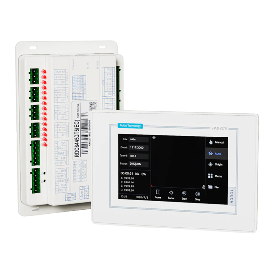
Page 15: Mainboard Physical Pictures
RDC6445GT5 Laser cutting system hardware user manualV1.1 3.1 Mainboard Physical pictures For more detailed pin description, see Chapter 4 Interface Signal Description. Figure 3.1-1 Mainboard Physical pictures 深圳市睿达科技有限公司... -
Page 16: Touch Screen Physical Pictures
RDC6445GT5 Laser cutting system hardware user manualV1.1 3.2 Touch screen Physical pictures Figure 3.2-1 Panel Physical pictures 深圳市睿达科技有限公司... -
Page 17: Control System Electrical Connectivity Diagram
RDC6445GT5 Laser cutting system hardware user manualV1.1 3.3 Control System Electrical Connectivity Diagram Figure 3.3-1 Control system electrical connectivity diagram 深圳市睿达科技有限公司... -
Page 18: Chapter 4 Mainboard Interface Signal Description
RDC6445GT5 Laser cutting system hardware user manualV1.1 Chapter Mainboard Interface Signal Description CONTENTS: Main Power Interface CN0 Mainboard and touch screen Connection Port HMI U disk Interface PC-USB Interface Ethernet Interface General/Dedicated Output Port CN1 Dedicated/General Input Interface CN2 Four-Axis Limit Input... - Page 19 RDC6445GT5 Laser cutting system hardware user manualV1.1 4.1 Main Power Interface CN0 Signal Definition GND (input) +24V 24V Power positive (input) This system adopts a single 24V power supply. It is recommended to use a power supply above 24V/2A. Meanwhile, this control system is Caution compatible with a 36V power supply.
-
Page 20: General/Dedicated Output Port Cn1
RDC6445GT5 Laser cutting system hardware user manualV1.1 4.6 General/Dedicated Output Port CN1 General/Dedicated output port definition Signal Definition GND (output) Out2 General output, reserved. Out1 General output, reserved. Dedicated output, working status signal port (or the second way pen signal). When it is an active status signal, if the port is... -
Page 21: Four-Axis Limit Input Interface Cn3/Cn4
RDC6445GT5 Laser cutting system hardware user manualV1.1 time is no less than 100ms, if the machine is idle currently, it will start work. If the machine is running currently, the work will be suspended. If the machine is in a paused state currently, the suspended work will be restarted, that is, the function of the foot switch is similar to the “Start/Pause”... -
Page 22: X/Y/Z/U Four-Axis Driver Interface Axis_X~Axis_U
RDC6445GT5 Laser cutting system hardware user manualV1.1 positive. If the limit polarity is set incorrectly, the limit will not be detected when the system is reset, resulting in shaft collision. Z/U axis limit interface CN3, pin definition is similar to X/Y axis limit interface CN4. - Page 23 RDC6445GT5 Laser cutting system hardware user manualV1.1 (the second laser power interface is CN6, and the pin definition is similar to CN5): Signal Definition Laser power ground (output) Laser enable control interface 1.When the laser source is a RF laser source, this pin is not used;...
-
Page 24: Overview
RDC6445GT5 Laser cutting system hardware user manualV1.1 Chapter 5 Examples of Laser Power Interface CONTENTS: Overview Glass Tube Laser Power Supply Wiring Diagram RF CO2 Laser Source Wiring Diagram 深圳市睿达科技有限公司... - Page 25 RDC6445GT5 Laser cutting system hardware user manualV1.1 5.1 Overview This control system has two independent and adjustable laser power supply control interfaces, which can control the glass tube laser power supply and RF CO2 laser source. When connecting different types of laser power supply, please set the laser source type correctly in the factory parameters, otherwise it may cause the laser.
-
Page 26: Rf Co2 Laser Source Wiring Diagram
RDC6445GT5 Laser cutting system hardware user manualV1.1 5.3 RF CO2 laser source wiring diagram 深圳市睿达科技有限公司... - Page 27 RDC6445GT5 Laser cutting system hardware user manualV1.1 Chapter 6 Examples of Stepping Motor Driver Interface CONTENTS: Overview Driver connection diagram 深圳市睿达科技有限公司...
- Page 28 Figure 6.1-1 and Figure 6.1-2. Each motor driver interface of Ruida product model RDC644XG mainboard provides a direction signal, a pulse signal and a 5V signal for common anode connection. Both pulse signal and direction signal are OC output.
- Page 29 RDC6445GT5 Laser cutting system hardware user manualV1.1 RDC644XG only supports the common anode connection, and cannot use common cathode or differential connection. The polarity of the direction signal can be set through the PC, and whether the pulse signal is valid at the rising edge or the falling edge can also be set via the PC.
-
Page 30: Driver Connection Diagram
RDC6445GT5 Laser cutting system hardware user manualV1.1 6.2 Driver Connection Diagram 深圳市睿达科技有限公司... -
Page 31: Chapter 7 Io Port Wiring Examples
RDC6445GT5 Laser cutting system hardware user manualV1.1 Chapter 7 IO Port Wiring Examples CONTENTS: Input Port Output Port 深圳市睿达科技有限公司... - Page 32 RDC6445GT5 Laser cutting system hardware user manualV1.1 7.1 Input port The two water protection input ports WP1 and WP2 of this controller are 24V logic, and all other input ports are compatible with input 5V/12V/24V logic voltage The connection diagram of the input port is as follows: Figure 7.1-1 Example of input port connection...
-
Page 33: Output Port
RDC6445GT5 Laser cutting system hardware user manualV1.1 7.2 Output port All the output signals of this controller adopt optocoupler isolation technology, OC gate output, and its maximum drive capacity is 300mA, which can directly drive 6V/24V relays, light-emitting indicators, buzzer alarm devices, etc. -
Page 34: Chapter 8 Hmi Operation Instructions
RDC6445GT5 Laser cutting system hardware user manualV1.1 Chapter 8 HMI Operation Instructions CONTENTS: Introduction Main interface functions Manual function Menu function User/Factory parameter settings File management Program upgrade 深圳市睿达科技有限公司... - Page 35 RDC6445GT5 Laser cutting system hardware user manualV1.1 8.1 Introduction The operation panel is a 5-inch touch screen, with beautiful interface, smooth and friendly operation, high-cost performance, etc. The panel can depict the motion track of the controller in real-time, allowing the users to check the current processing graphics.
- Page 36 RDC6445GT5 Laser cutting system hardware user manualV1.1 8.2 Main interface functions 8.2.1 Main interface When the system is powered on and reset, the main interface will be displayed. As shown below: Figure 8.2.1 Graphic display area: this area is used for file preview display and for depicting the processed file image during processing.
- Page 37 RDC6445GT5 Laser cutting system hardware user manualV1.1 Start: start processing. Stop: stop processing. Keyboard lock: when clicking on the system time area, the interface will be locked, and the icon will be displayed on the screen. Clicking it the again to unlock successfully.
-
Page 38: File Parameters
RDC6445GT5 Laser cutting system hardware user manualV1.1 Figure 8.2.2-2 Parameters can be modified at this time, after modification, press the “OK” key to confirm the modification and return or press the “ESC” key to cancel the modification and return to the previous interface, and finally press the “OK”... -
Page 39: Layer Information
RDC6445GT5 Laser cutting system hardware user manualV1.1 Figure 8.3 On the right side of the interface is the menu bar, including “Layer”, “Properties” and “Main Interface”, which respectively indicate file layer information, file properties and return to the main interface. The layer menu is selected by default and marked in blue in the interface. Click “Main Interface”... - Page 40 RDC6445GT5 Laser cutting system hardware user manualV1.1 Figure 8.3.2 Repeat processing After clicking the “Repeat” button, the interface is shown in Figure 8.3.2. The number of repetitions means the number of repetitive processing, and the repetition delay means the time interval for the next start of processing. Once the repeat parameter is set to be valid, it is valid to all processing files.
- Page 41 RDC6445GT5 Laser cutting system hardware user manualV1.1 Figure 8.3.2-2 The list on the left of the interface is a list of all the array names contained in this file, which can view through the page button on the left. After selecting an array, the information will be displayed on the right at the same time.
-
Page 42: Manual Functions
RDC6445GT5 Laser cutting system hardware user manualV1.1 Figure 8.3.2-3 After clicking the “Working hours preview” button, the system calculates working hours for this file. If the file is relatively complicated, calculation time will increase accordingly, please wait in patience here. -
Page 43: Frame Function
RDC6445GT5 Laser cutting system hardware user manualV1.1 distance (not 0) is set, the axis will start to move after pressing the button, and the axis will continue to move until the set inching distance is reached after releasing the button. The fast and slow key ( ) can switch the shaft motion speed, when F is blue, it is fast, otherwise it is slow. - Page 44 RDC6445GT5 Laser cutting system hardware user manualV1.1 Figure 8.4.3 There are three options for frame mode: laser on, laser off and four-corner dotting. After selecting the mode, press the “Cut Frame” key to start and press the “Stop” key to stop.
-
Page 45: Reset Function
RDC6445GT5 Laser cutting system hardware user manualV1.1 8.4.5 Reset function Click the “Reset” key to reset the system and return to zero for each axis, etc. 8.5 Menu function Click the “Menu” button in the main interface and enter the menu interface, as shown below: Figure 8.5... - Page 46 RDC6445GT5 Laser cutting system hardware user manualV1.1 Figure 8.5.1-1 This interface includes mainboard information, product activation and time setting functions. Product activation: enter the lower-lever product activation interface. Figure 8.5.1-2 After modifying the authorization code, press the OK key to modify the authorization, and cancel to return the upper interface.
- Page 47 RDC6445GT5 Laser cutting system hardware user manualV1.1 After modifying the time, press the OK key to modify the time, and cancel to return to the upper interface. When the system is in an encrypted state, the time can not be modified.
- Page 48 RDC6445GT5 Laser cutting system hardware user manualV1.1 2.Input the coordinates that need to be set as the positioning point in the edit box for the positioning point X(mm), and positioning point Y(mm). If user not sure whether the input coordinates are the position you want, click the “Move to Positioning Point”...
- Page 49 RDC6445GT5 Laser cutting system hardware user manualV1.1 system uses a single positioning point logic. Press the “Position” key on the keyboard to set the positioning point, and only the setting positioning point takes effect. When “Yes” is selected, system uses a multi-positioning point logic, and the “Position” key on the keyboard is invalid.
- Page 50 RDC6445GT5 Laser cutting system hardware user manualV1.1 Figure 8.5.1-7 This is the backup parameter function. If the current set parameters need to be backed up, click the blue button on the screen, and enter the password input interface as shown in Figure 8.5.1-7: Input the password and wait for the backup to succeed.
- Page 51 RDC6445GT5 Laser cutting system hardware user manualV1.1 Figure 8.5.1-9 This is the restore parameter function. If you need to restore the parameters, click the blue button on the screen, and enter the password input interface as shown in Figure 8.5.1-9: Figure 8.5.1-10...
-
Page 52: Language Settings
RDC6445GT5 Laser cutting system hardware user manualV1.1 Figure 8.5.1-11 Set the origin position of the display screen here. Choose different screen origin positions to mirror the displayed graphics in different X/Y directions. To set the origin position of the display screen, just click the corresponding position button. - Page 53 RDC6445GT5 Laser cutting system hardware user manualV1.1 Figure 8.5.3-1 User parameters include cutting parameters, engraving parameters, focusing parameters, reset parameters and return parameters. Parameter modification method: 1.If it is a numeric class parameter, a numeric keyboard will appear after clicking the parameter area, as shown in the figure below: Figure 8.5.3-2...
- Page 54 RDC6445GT5 Laser cutting system hardware user manualV1.1 Figure 8.5.3-3 Select the item to be set, and then click OK, the parameter selection box disappears, and the parameter modification is completed. Other parameter interfaces are as follows: For details of the parameters, please refer to Chapter 9.
- Page 55 RDC6445GT5 Laser cutting system hardware user manualV1.1 Figure 8.5.4-1 Factory parameters includes: feeding parameters, rotation parameters, Z-axis control, speed parameters, system configuration, machine parameters, axis parameters and laser parameters. Select one of these interfaces to display all parameters of this type, and user can scroll through the pages through the page button on the left.
-
Page 56: File Management
RDC6445GT5 Laser cutting system hardware user manualV1.1 Factory parameter setting method is the same as the user parameter, please refer to Chapter 9 for detailed parameter explanation. 8.9 File management 8.9.1 Memory file In the main interface, press the “File” , the following interface pops up: Figure 8.9.1... - Page 57 RDC6445GT5 Laser cutting system hardware user manualV1.1 Memory: switch to file interface and read file. U disk: switch to U disk interface and read U disk files. Copy: copy the selected file to U disk. Delete: delete the selected file ...
-
Page 58: Program Upgrade
RDC6445GT5 Laser cutting system hardware user manualV1.1 8.10 Program upgrade 8.10.1 Touch screen program Upgrade Software upgrade Open the system supporting software RDWorksV8, and successively select “Settings”, “System settings” and “Mainboard Information” in the upper menu bar, as shown in the figure below: Figure 8.10-1-1... - Page 59 RDC6445GT5 Laser cutting system hardware user manualV1.1 Figure 8.10.1-2 Select “Touch Screen HMI (*.hmt)” as the file type, select update.hmi file, and finally click the “Open” button to start the upgrade. SD Card upgrade The panel supports using the SD card to upgrade the program with the steps as follows: 1.Prepare a micro SD card...
- Page 60 RDC6445GT5 Laser cutting system hardware user manualV1.1 1.Prepare a U disk in FAT32 format. 2.Copy the update.hmt file in the the root directory of the U disk, and then insert the U disk into the USB interface of the mainboard.
- Page 61 RDC6445GT5 Laser cutting system hardware user manualV1.1 Figure 8.10.2-1 Select 800X480(TFT) as the panel type, and then click “Import Bitmap”, as shown in the figure below: Figure 8.10.2-2 File types support jpg, bmp and other formats. Select a picture and click the “Open” button, as shown in the figure below: 深圳市睿达科技有限公司...
- Page 62 RDC6445GT5 Laser cutting system hardware user manualV1.1 Figure 8.10.2-3 Then click the “Download” button to start the upgrade, and the upgrade progress will be displayed on the panel. After upgrade completed, it prompts that the upgrade is successful. User can check the updated boot screen after restart.
- Page 63 RDC6445GT5 Laser cutting system hardware user manualV1.1 Figure 8.10.3-1 Click the “Mainboard Upgrade” button to pop up the following interface: Figure 8.10.3-2 Select RDC6445.upd file, and then click the “Open” button to start upgrading, the upgrade progress will be displayed on the touch screen. After the upgrade is completed, it prompts that the upgrade is...
- Page 64 RDC6445GT5 Laser cutting system hardware user manualV1.1 successful, and the system needs to be powered on again. U disk upgrade The steps to upgrade the U disk are as follows: 1.Prepare a U disk in FAT32 format. 2.Copy the RDC6445.upd file to the root of the U disk, and insert the U disk into the USB interface of the mainboard.
- Page 65 RDC6445GT5 Laser cutting system hardware user manualV1.1 Chapter 9 Vendor / User Parameters CONTENTS: Vendor parameters User parameters 深圳市睿达科技有限公司...
-
Page 66: Vendor Parameters
RDC6445GT5 Laser cutting system hardware user manualV1.1 9.1 Vendor parameters (1)Motor parameters X/Y/Z/U axis parameters Direction polarity: modify the direction polarity to make the motor move in the reverse direction. The purpose of modification is to make the axis move to the origin when reset. - Page 67 RDC6445GT5 Laser cutting system hardware user manualV1.1 acceleration and deceleration. When the acceleration is set too large, it will also cause the motor to lose steps, shake and even howl; setting too small will cause slow acceleration and reduce the running speed of the entire graphics. Corresponding to the axis with large inertia, such as the Y axis corresponding to the beam, a typical setting range is 800~3000mm/s2.
- Page 68 RDC6445GT5 Laser cutting system hardware user manualV1.1 during operation, the maximum power set by the user can’t be higher than the maximum power value set here, and the minimum power value set by the user cannot be lower than the minimum power value set here;...
- Page 69 RDC6445GT5 Laser cutting system hardware user manualV1.1 After modifying the configuration parameters in the factory parameters, such as direction polarity, control method, laser source type and laser frequency, the system needs to be reset, and the modification takes effect when the reset Prompt is completed.
-
Page 70: User Parameters
RDC6445GT5 Laser cutting system hardware user manualV1.1 9.2 User parameters (1)Cutting parameters (only affect the cutting mode) Idle speed: this parameter determines the highest speed of all laser-off straight lines during the motion of the machine. Idle acceleration: the highest acceleration of the laser-off straight lines. Larger setting of idle speed and idle acceleration can shorten the working time of the entire graph. - Page 71 RDC6445GT5 Laser cutting system hardware user manualV1.1 achieved, and the high-power short-time light output mode will have a certain influence on the life of the laser source. The system defaults to select the general mode. 。 Light spot size: when the general mode is selected as the scan mode, this parameter is invalid;...
- Page 72 RDC6445GT5 Laser cutting system hardware user manualV1.1 determines the parking position of the laser head after completing each work. Focal length: the distance from the focal point of the laser head lens to the origin of the Z axis. ...
-
Page 73: Chapter 10 Common Problems And Solutions
RDC6445GT5 Laser cutting system hardware user manualV1.1 Chapter 10 Common Problems and Solutions CONTENTS: Common problems Alarm information 深圳市睿达科技有限公司... - Page 74 RDC6445GT5 Laser cutting system hardware user manualV1.1 10.1 Common problems Q: The direction of the graphics displayed on the panel is inconsistent with the one displayed by the PC software? A: this situation is generally caused by the inconsistency between the screen origin and the origin set by the mainboard;...
- Page 75 RDC6445GT5 Laser cutting system hardware user manualV1.1 10.2 Alarm information The system will detect faults in real time and prompt the corresponding information or alarms to avoid unnecessary losses. The alarm information is described as below: Alarm type Reasons Solutions...
- Page 76 RDC6445GT5 Laser cutting system hardware user manualV1.1 Thank you for your selection of our production! All the copyright of this manual is owned by Ruida technology. Any person or company can not copy upload and send the manual without Ruida’s permission.
Need help?
Do you have a question about the RDC6445GT5 and is the answer not in the manual?
Questions and answers