Table of Contents
Advertisement
Advertisement
Table of Contents

Related Manuals for RuiDa KT332N


Summary of Contents for RuiDa KT332N
- Page 1 KT332N Cutting &engraving control system user manual V1.1 Users should read this manual before using the controller. This manual contents is the system operation manual Read this manual carefully to ensure proper electrical connection KT332N Laser cutting&engraving control system user manual...
- Page 2 KT332N Cutting &engraving control system user manual V1.1 NOTICE We reserves the right to modify the products and product specifications in this manual without prior notice, and reserves the right to modify any documents attached to this product. Users should read this manual carefully when using the products described in this article.
- Page 3 KT332N Cutting &engraving control system user manual V1.1 CERTIFICATION STATEMENT CE Certification statement This product has passed the European Union CE (Communate Europpene) safety certification, has passed the corresponding conformity assessment procedures and the manufacturer's declaration of conformity, and complies with the relevant EU directives.
- Page 4 KT332N Cutting &engraving control system user manual V1.1 SAFETY INFORMATION Please make sure that the operation is correct and the method is safe when using the system. Some signs or words will be used to remind you of dangerous matters and some important information.
- Page 5 If you notice any obvious damage to the device, do not install the device or commission the device. KT332N cutting system delivery list is shown in the following: ( As the product is constantly updated, the accessories that may be received are difference)...
-
Page 6: Table Of Contents
KT332N Cutting &engraving control system user manual V1.1 Contents Chapter 1 Overview............................. 1 1.1 KT332N introduction..........................2 Chapter 2 Controller dimension......................3 2.1 Dimension of controller.........................4 2.2 Dimension of pannel..........................4 Chapter 3 Overview of the product......................6 3.1 Controller overview..........................7 3.2 Panel Overview............................7... - Page 7 KT332N Cutting &engraving control system user manual V1.1 8.6.3 Frame setting............................30 8.6.4 Blow Setting............................30 8.6.5 Speed setting............................34 8.6.6 Machine configuration........................30 8.6.7 Rotate function settings........................30 8.6.8 Jog settings............................30 8.6.9 Pulse setting............................. 30 8.6.10 Axis reset............................34 8.6.11 Multiple points positioning setting....................35 8.6.12 Screen origin setting........................
-
Page 8: Kt332N Introduction
KT332N Cutting &engraving control system user manual V1.1 Chapter 1 Introduction MAIN CONTENTS OF THIS CHAPTER: KT332N Introduction... - Page 9 KT332N Cutting &engraving control system user manual V1.1 1.1 KT332N Introduction to Control System KT332N control system is the latest generation of standalone laser engraving and cutting control system developed by our company. This control system has better stability and anti-interference performance.
-
Page 10: Chapter 2 Controller Dimension
KT332N Cutting &engraving control system user manual V1.1 Chapter 2 Controller dimension MAIN CONTENTS OF THIS CHAPTER: Dimension of controller Dimension of Panel... -
Page 11: Dimension Of Controller
KT332N Cutting &engraving control system user manual V1.1 2.1 Dimension of controller All dimensions are in mm, accurate to 0.1mm (four of the positioning holes are symmetrical) 2.2 Dimension of panel All dimensions are in mm, accurate to 0.1mm... - Page 12 KT332N Cutting &engraving control system user manual V1.1...
-
Page 13: Chapter 3 Overview Of The Product
KT332N Cutting &engraving control system user manual V1.1 Chapter 3 Overview of the product MAIN CONTENTS OF THIS CHAPTER: Controller overview Panel overview Electrical connection diagram... -
Page 14: Controller Overview
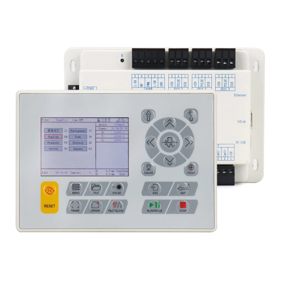
KT332N Cutting &engraving control system user manual V1.1 3.1 Controller overview For more detailed pin description, see Chapter 4 Interface Signal Description 3.1-1 controller 3.2 Panel overview 3.2-1 panel... - Page 15 KT332N Cutting &engraving control system user manual V1.1 3.3 Electrical connection diagram of control system 3.3-1 Electrical connection diagram of control system...
-
Page 16: Chapter 4 Controller Specification
KT332N Cutting &engraving control system user manual V1.1 Chapter 4 Controller specification MAIN CONTENTS OF THIS CHAPTER: Main power interface POWER Controller and panel interface HMI U-disk interface PC-USB interface General and dedicated OUTPUT General and dedicated INPUT Limit input interface LIMIT... -
Page 17: Pc-Usb Interface
PC-USB is a communication port that can build up the communication between the controller and the computer. It supports USB2.0 protocol. 4.5 Ethernet port KT332N has the Ethernet port and USB port. KT332G only have USB port. 4.6 General and dedicated output General and dedicated output definition... - Page 18 KT332N Cutting &engraving control system user manual V1.1 assigned as second pen control. the multiplexing function is also enabled by auxiliary air control is enabled or not. Output is an open collector type. When working, this output connect to GND.
-
Page 19: Laser Power Control Interface Laser
KT332N Cutting &engraving control system user manual V1.1 LmtU- U-,U axis moves to the limit at 0 coordinate LmtY- Y-,Y axis moves to the limit at 0 coordinate LmtX- X-,X axis moves to the limit at 0 coordinate Power + 5V (output) On the controller, only one limit switch is needed. - Page 20 KT332N Cutting &engraving control system user manual V1.1 protection 1. Water protection input must use 24V voltage input Laser power analog signal output. For glass tube laser power L-AN supply, it is recommended to use this pin for power signal.
-
Page 21: Chapter 5 Example Of Laser Power Interface
KT332N Cutting &engraving control system user manual V1.1 Chapter 5 Laser power interface MAIN CONTENTS OF THIS CHAPTER: Overview Glass tube laser power wiring diagram -RF CO2 laser wiring diagram... -
Page 22: Overview
KT332N Cutting &engraving control system user manual V1.1 5.1 Overview This control system has two independently adjustable laser power control interfaces, which can control glass tube laser power and RF CO2 laser. When connecting different laser power types, please set the laser type correctly in the factory parameters, otherwise it cause to the switching light may be incorrect. - Page 23 KT332N Cutting &engraving control system user manual V1.1...
-
Page 24: Chapter 6 Example Of Stepper Motor Driver Interface
KT332N Cutting &engraving control system user manual V1.1 Chapter 6 Stepper motor driver interface MAIN CONTENTS OF THIS CHAPTER: overview Step motor wiring diagram... -
Page 25: Overview
KT332N Cutting &engraving control system user manual V1.1 6.1 Overview KT332N only supports the common anode connection method, and common cathode is not suggested. Figure 6.1-1 Four-input, driver input Figure 6.1-2 Three inputs, common input signal is independent signal of driver PU+ and DR+ are usually connected to +5V and the PU-, DR- are connecting with the signal port on the controller. -
Page 26: Drive Wiring Diagrams
KT332N Cutting &engraving control system user manual V1.1 6.2 Drive wiring diagram... - Page 27 KT332N Cutting &engraving control system user manual V1.1 Chapter 7 IO wiring MAIN CONTENTS OF THIS CHAPTER: General and dedicated input General and dedicated output...
-
Page 28: Input
KT332N Cutting &engraving control system user manual V1.1 7.1 Input The water protection input port WP of this controller is only compatible with 24V. All other input ports are compatible with input 5V / 12V / 24V. The wiring diagram of the input port is as follows: Figure 7.1-1... -
Page 29: Output
KT332N Cutting &engraving control system user manual V1.1 7.2 Output All output signals of this controller are output based on opto-coupler isolation technology and OC gate output. Its maximum driving capacity is 300mA, which can directly drive 6V / 24V relays, light-emitting indicators, buzzer alarm devices, etc. -
Page 30: Chapter 8 Hmi Operation Instructions
KT332N Cutting &engraving control system user manual V1.1 Chapter 8 HMI operation MAIN CONTENTS OF THIS CHAPTER: Introduction Main interface functions Speed setting Power setting Layer function Manu function File management Password entry and setting Tips and alarms Parameter setting operation... -
Page 31: Introduction
8.1 Introduction 8.1.1 Overview KT332N-HMI panel (hereinafter referred to as "panel") is a HMI interface based on a 3.5 TFT LCD screen. The panel can display cutting path in real time, allowing users to understand the current processing patterns, supporting file management, file preview, parameter modification, and support for switching between multiple language interfaces. -
Page 32: Key Function Description
KT332N Cutting &engraving control system user manual V1.1 8.1.2 Key Function Description “RESET”:Reset system “RUN/PAUSE”:Start job or pause / restart job “PULSE”:Laser tube pulse “STOP”:Stop processing/Motor axis movement “FOCUS”:Auto Focus “MANU”: User parameters, manufacturer parameters, language settings, etc. -
Page 33: Main Interface Functions
KT332N Cutting &engraving control system user manual V1.1 “AUX.AIR”: For controlling air blowing “FAST/SLOW”: Used to set the fast and slow speed of the keys. When user presses the arrow key (manual move) directly, it will be slow; when you press and hold the “FAST/SLOW”... -
Page 34: Speed Setting
KT332N Cutting &engraving control system user manual V1.1 In the completed / idle state, the keys can respond, and users can perform file processing, parameter setting, file preview and other operations. In the running / pause state, some keys do not respond, such as positioning key, border key, file key, etc. -
Page 35: Layer Function
KT332N Cutting &engraving control system user manual V1.1 Figure 8.4-2 Press ENT again, the following interface pops up: Figure 8.4-3 Refer to Section 8.10 for parameter setting operation. After setting, press [ENT] to save the modified parameters, and press the [Esc] key to exit the interface. -
Page 36: Menu Function
KT332N Cutting &engraving control system user manual V1.1 Figure 8.5-2 User can press the up and down keys to select the layer number, and the "select block" will also move. Select the layer number to be modified and press [ENT] ,the layer setting interface will pop up, as shown in the figure below: Figure 8.5-3... -
Page 37: Parameter Settings
KT332N Cutting &engraving control system user manual V1.1 Figure 8.6 Press [ENT] to enter the lower menu, and press [Esc] to return to the previous menu. 8.6.1 Parameters setting Press [Parameter Setting] in the menu interface, and the parameter setting interface pops up as follows: Figure 8.6... -
Page 38: Motion Parameter
KT332N Cutting &engraving control system user manual V1.1 8.6.1.1Motion parameter In the parameter setting interface, press [Movement parameter] , and the movement parameter setting interface will pop up as follows: Figure8.6.1-1 Refer to Section 8.10 for parameter setting operation. Press the [Esc] key. The interface exit and returns to the previous interface. -
Page 39: Blow Setting
KT332N Cutting &engraving control system user manual V1.1 8.6.1.3 Blow Setting In the parameter setting interface, press [Blow Setting], and the blowing setting interface pops up as follows: 8.6.1-3 Refer to Section 8.10 for parameter setting operation. Press the [Esc] key. The interface exit and returns to the previous interface. -
Page 40: Rotate Function Settings
Figure 8.6.1-6 Refer to Section 8.10 for parameter setting operation. Press the [Esc] key. The interface exit and returns to the previous interface. 8.6.1.7 IP Set KT332G do not support Ethernet. Only KT332N can support Ethernet and USB. -
Page 41: Jog Settings
KT332N Cutting &engraving control system user manual V1.1 Figure8.6.1-7 When the IP is changed, user should <Write > make the parameter valid. 8.6.1.7Jog settings When the red selection box is stopped on the item and press [OK] key, the following interface pops up: Figure 8.6.2... -
Page 42: Pulse Setting
KT332N Cutting &engraving control system user manual V1.1 8.6.9 Laser pulse setting When the red selection box is stopped on the item and presses the [OK] key, the following interface pops up: Figure 8.6.3 If the continuous shooting mode is selected, the laser will always on when press the continuous button. - Page 43 KT332N Cutting &engraving control system user manual V1.1 prompts "Resetting ...". Press the [Esc] key to return to the previous menu. 8.6.11 Multiple origin points setting In the menu, select the item “Origin point setting” and press the [OK] key to pop up the following interface: Figure 8.6.5-1...
- Page 44 KT332N Cutting &engraving control system user manual V1.1 There are 4 origin points that can be set. The steps are that same as above when set other 3 origin points. User can select one of the 4 origin points as the start origin point. When the "selection box" stops at the "start origin", press the [OK] key to confirm the modification, press the "Up / Down"...
- Page 45 KT332N Cutting &engraving control system user manual V1.1 Figure 8.6.6 Set the reference position of the screen here. Select different reference positions of the screen to correctly display the patterns. Select a reference position and press the [OK] key. The setting takes effect and the system returns to the main interface automatically.
-
Page 46: Language Settings
KT332N Cutting &engraving control system user manual V1.1 password to lock the keys. Keyboard lock This item can lock the keys. After entering the correct password, the keys are automatically locked and returned to the main interface. When any key is pressed, the interface prompts for the password to unlock the keys. -
Page 47: System Information
KT332N Cutting &engraving control system user manual V1.1 Figure 8.6.9 This interface displays the system's hardware IO port information: trigger normal INPUT: Read the system hardware information. When the hardware signal is triggered, the small box to the left of the corresponding entry will be displayed in red, otherwise it will be displayed in gray. -
Page 48: Backup Factory Parameters
KT332N Cutting &engraving control system user manual V1.1 8.6.17 Backup factory parameters Select the "Backup factory parameters" item in the menu interface, and press the [OK] key to pop up the password interface. For password input operations, refer to section 8.8. If the password is entered correctly, the system will back up all current factory parameters and user parameters to factory parameters, the interface prompts “set parameters successfully". -
Page 49: Time Setting
KT332N Cutting &engraving control system user manual V1.1 the Udisk. <restore para from U disk>: restore the vendor and user parameters from the Udisk. <upgrade from U disk>: upgrade the controller firmware from the U disk. 8.6.20 Time setting When the "red selection box" is stopped on the item and press [OK] , the following interface pops This interface is only displayed when the system is not encrypted. -
Page 50: File Management
KT332N Cutting &engraving control system user manual V1.1 Figure 8.6.14-2 Use the “Up, Down, Left, Right” to select the corresponding character. If the operation is incorrect and the input is wrong, just press [Esc] and select [OK] to enter the setting again. The red selection box selects the currently modified parameter box, and presses the arrow keys to select other parameter boxes. -
Page 51: File Parameters
KT332N Cutting &engraving control system user manual V1.1 files, press the up and down keys to select a file, the file will be previewed, and the graphic will be displayed in the upper right of the interface. After pressing [OK], the file will be previewed on the main interface, and the current file dialog box will be closed. -
Page 52: Auto Feeding Parameters
KT332N Cutting &engraving control system user manual V1.1 Figure 8.7.2.1-1 Then select any items in the interface above, and press [OK], and then the pop-up menu is as shown below: Figure 8.7.2.1-2 Refer to Section 8.10 for parameter setting operation. Press the [Esc] key to cancel parameter modification and return to the previous interface. -
Page 53: Memory Operation
KT332N Cutting &engraving control system user manual V1.1 Figure 8.7.2.2 Refer to Section 8.10 for parameter setting operation. 8.7.5 Memory operation Select the "Memory Operation" item in the interface above, and the pop-up menu is as shown below: Figure 8.7.3 Current work time: Preview the processing time of the currently selected file. -
Page 54: U Disk File
KT332N Cutting &engraving control system user manual V1.1 Figure 8.7.4 After formatting the memory, all memory files will be erased. 8.7.6 U disk file Select the "U disk file" entry on the "File" interface and press [OK] to pop up the U disk file list, as shown in the figure: Figure 8.7.5... -
Page 55: Password Input And Setting
KT332N Cutting &engraving control system user manual V1.1 from the controller to the U disk are placed in the root directory of the U disk. 8.8 Password and setting 8.8.1 Password You need to enter a password when operations. The pop-up interface is as follows: Figure 8.8.1... -
Page 56: Parameter Setting Operation
KT332N Cutting &engraving control system user manual V1.1 passwords, press the [OK] key to perform the operation, otherwise "Password Error" is displayed, and input the password again. 8.9 Alarms information During the system is working, some alarm or messages will pop up, such as resetting, water protection fault, hard limit protection, border crossing, etc when executing some actions. - Page 57 KT332N Cutting &engraving control system user manual V1.1 Figure 8.10.1 8.10.1 Option Box operating When users modify the parameter of the selection parameter box, first select the parameter, and then press the OK key. The up and down arrows appear on the right side of the selection parameter box.
- Page 58 KT332N Cutting &engraving control system user manual V1.1 digits before the hundredth to 0 When user need to set other digits, use the "up and down arrow keys" to select the parameter to be modified and perform. Note: The parameter box has a limit on the number of digits. When the parameter digit was...
-
Page 59: Chapter 9 Detailed Manufacturer / User Parameters
KT332N Cutting &engraving control system user manual V1.1 Chapter 9 Vendor and user parameters introduction MAIN CONTENTS OF THIS CHAPTER: Vendor parameters User parameters... -
Page 60: Vendor Parameters
KT332N Cutting &engraving control system user manual V1.1 9.1 Vendor parameters All the vendor parameters can be modified by the software! (1)Motor parameters X, Y, Z, U axis parameters Direction polarity :Modifying the direction polarity can make the motor move in the ... - Page 61 KT332N Cutting &engraving control system user manual V1.1 increased. Typical values are 5 ~ 30mm / s. Maximum speed : The maximum limit of speed that the shaft can withstand. This parameter is related to the driving ability of the motor, the inertia of the moving shaft, and the transmission ratio.
- Page 62 KT332N Cutting &engraving control system user manual V1.1 the controller will not detect The laser frequency is used to set the pulse frequency of the control signal used by the laser. The glass tube is generally set to about 20KHZ and the RF tube is generally set to about 5KHZ.
-
Page 63: User Parameters
KT332N Cutting &engraving control system user manual V1.1 9.2 User parameters All the user parameters can be modified by the software! (1)Cutting parameters(Only affects for cutting works) Fast feed speed:This parameter determines the maximum speed of all straight lines ... - Page 64 KT332N Cutting &engraving control system user manual V1.1 the life of the laser. The system selects the general mode by default. Aperture size : When the general mode is selected for the scanning mode, this parameter is invalid. When the special mode is selected, this parameter becomes effective.
- Page 65 KT332N Cutting &engraving control system user manual V1.1 (6)Other user parameters Array processing method:Two-way array and one-way array can be selected, which only works for virtual array. Bidirectional walking array: the array is cut back and forth in sequence; unidirectional walking array: the array is always cut from one direction to the other.
Need help?
Do you have a question about the KT332N and is the answer not in the manual?
Questions and answers
what verison of rdworks is required
The required version of RDWorks for RuiDa KT332N is not specified in the provided context.
This answer is automatically generated
I have this controller in my Monport 100w CO2 Laser and trying to cut 1/4 red oak.... the material test resulted in successful cuts at 0.1 in per sec for 32.5% and above, and single pass .... when I go to do the actual cut in a larger shape - those settings don't even come close to working trying to figure out if I have a setting wrong in Lightburn or the laser
I keep getting the error message: need more overshooting or larger acceleration