Table of Contents
Advertisement
Advertisement
Table of Contents

Subscribe to Our Youtube Channel
Related Manuals for RuiDa RDC644XG


Summary of Contents for RuiDa RDC644XG
- Page 1 RDC644XG Controller User Manual Shenzhen RuiDa Technology CO., LTD Tel: 86- 0755-26066687 Fax: 86-0755-26982287 Web: www.rd-acs.com E-Mail: support@rd-acs.com Add: 1B-1, Building 5, Tian'an Nanyou Industry Area, Dengliang Road, Nanshan District, Shenzhen, P.R.C.
-
Page 2: Copyright Declaration
2. Ruida Technology is entitled to increase or reduce and modify the products and functions of this product stated herein as well as amend any documents attached to this product, without prior notification. -
Page 3: Table Of Contents
4.10 Laser Power Control Interface CN5/CN6..............18 Chapter 5 Examples of Laser Power Interface..................20 5.1 Brief Introduction......................20 5.2 Examples of Glass tube Laser Power................21 5.3 Examples of RF- CO2 Laser...................22 3 / 51 © 2016 Ruida Technology. All Rights Reserved. - Page 4 8.3.11 IP Setup............................37 8.3.12 Diagnoses............................38 8.3.13 Screen Origin..........................39 8.4 File Key.......................... 39 8.4.1 Memory File............................39 8.5 Alarm Info........................42 Chapter 9 Manufacturer/User Parameters Details................44 9.1 Manufacturer Parameters....................44 9.2 User Parameters......................47 4 / 51 © 2016 Ruida Technology. All Rights Reserved.
- Page 5 RDC644XG Controller User Manual 5 / 51 © 2016 Ruida Technology. All Rights Reserved.
-
Page 6: Chapter 1 Overview
Chapter 1 Overview 1.1 Briefing RDC644XG system is a new generation system for control of laser engraving and cutting, which is developed by RD technology, Ltd. High hardware stability, high voltage or static electricity rejection, and friendly 3.5TFT man-machine display. This system is provided with stronger... -
Page 7: Comparison Of Controller Performance
OC output, each, OC output, output, reverse drive no reverse current no reverse current current protection needed) protection) protection) included) Power-off Software restart Feature Engraving Multi-origin Logics Parameter 7 / 51 © 2016 Ruida Technology. All Rights Reserved. - Page 8 320*240 320*480 TFT display type display display display Soft Limit Motion-axis Feature Hard Limit Z-axis Linkage Feeding Single Single/double Single/double Single/double Feature direction direction for option direction direction for option 8 / 51 © 2016 Ruida Technology. All Rights Reserved.
- Page 9 PC time hardware integrated included encryption hardware encryption Communicat USB2.0 10/100MHZ 10/100MHZ 10/100MHZ Ethernet Ethernet or USB2.0 Ethernet USB2.0, Mode USB2.0 communication mode automatically checked 9 / 51 © 2016 Ruida Technology. All Rights Reserved.
-
Page 10: Chapter 2 Installation Size
Chapter 2 Installation Size 2.1 Installation Size of Controller The unit of all sizes is millimeter (mm) and the size accurate to 0.1mm (the four holes are symmetrical). Figure 2.1-1 10 / 51 © 2016 Ruida Technology. All Rights Reserved. -
Page 11: Size Of Panel
RDC644XG Controller User Manual 2.2 Size of Panel The unit of all sizes is millimeter (mm) and the size accurate to 0.1mm. Figure 2.2-1 11 / 51 © 2016 Ruida Technology. All Rights Reserved. -
Page 12: Chapter 3 Controller Real Picture And Interface
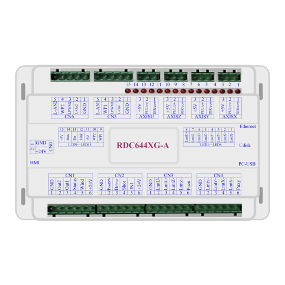
Chapter 3 Controller Real Picture and Interface 3.1 Picture of Controller For more detailed pin description, see the Chapter 4: Description of Interface Signal for Controller. Figure: 3.1-1 Picture of Controller 12 / 51 © 2016 Ruida Technology. All Rights Reserved. -
Page 13: Pictures Of Panel
RDC644XG Controller User Manual 3.2 Pictures of Panel Figure: 3.2-1 Picture of Panel 13 / 51 © 2016 Ruida Technology. All Rights Reserved. -
Page 14: Electrical Connection Of Control System
RDC644XG Controller User Manual 3.3 Electrical Connection of Control System Figure 3.3-1 Electric Connection 14 / 51 © 2016 Ruida Technology. All Rights Reserved. -
Page 15: Chapter 4 Interface Signal Of Controller
PC-USB is a USB-BM interface. The controller may communicate with PC by this port. 4.5 Ethernet Interface Using this interface, the controller can communicate with PC by 10/100MHZ Ethernet. Pin to Pin Ethernet parallel line is recommended. Caution 15 / 51 © 2016 Ruida Technology. All Rights Reserved. -
Page 16: General /Dedicated Output Port Cn1
100 ms, if the machine lies idle, it can be started for work; if the machine is in the working state, the work will be suspended; of the machine is in the suspension, the work will 16 / 51 © 2016 Ruida Technology. All Rights Reserved. -
Page 17: 4-Axis Limit Input Interface Cn3/Cn4
The mistaken setting of limit polarity will result that the limit can’t be detected when the system is reset so as to lead to the collision of axis. 17 / 51 © 2016 Ruida Technology. All Rights Reserved. -
Page 18: X/Y/Z/U-Axis Motor Driver Interface Axis_X~Axis_U
2. When the laser is a glass tube, if the used laser is outputted in the low-level form, this pin will be connected with the laser power enable end and used to control the ON/Off of laser. LPWM1 Power control interface of laser/laser tube 18 / 51 © 2016 Ruida Technology. All Rights Reserved. - Page 19 The analog signals for Laser Power. If Glass Tube is used, this pin is recommended to control the power of the Laser. Please correctly select the laser type in the factory parameters. Prompt 19 / 51 © 2016 Ruida Technology. All Rights Reserved.
-
Page 20: Chapter 5 Examples Of Laser Power Interface
RF-laser. Please correctly select the laser type in the factory parameters when connecting to different laser types, otherwise, the laser switching is incorrect. 20 / 51 © 2016 Ruida Technology. All Rights Reserved. -
Page 21: Examples Of Glass Tube Laser Power
RDC644XG Controller User Manual 5.2 Examples of Glass tube Laser Power 21 / 51 © 2016 Ruida Technology. All Rights Reserved. -
Page 22: Examples Of Rf- Co2 Laser
RDC644XG Controller User Manual 5.3 Examples of RF- CO2 Laser 22 / 51 © 2016 Ruida Technology. All Rights Reserved. -
Page 23: Chapter 6 Interface Examples Of Step-Servo Motor Driver
4 external leading-out wires and some 3 wires (only the pulse and directional signals are counted) as shown in Figure 6.1-1 and 6.1-2. RDC644XG Controller has four groups of 3-wires motion driver interface, each interface has one direction signal, one pulse signal, and one 5V positive output, the direction signal and the pulse signal are all OC output. -
Page 24: Examples Of Motor Driver Connection
RDC644XG Controller User Manual 6.2 Examples of Motor Driver Connection 24 / 51 © 2016 Ruida Technology. All Rights Reserved. -
Page 25: Chapter 7 Examples Of Io-Port Wiring
The two water protection inputs are WP1 and WP2 with 24V logic level; all other inputs are compatible with 5V/12V/24V logic level. Input connection is shown as below: Figure 7.1-1 Input Example 25 / 51 © 2016 Ruida Technology. All Rights Reserved. -
Page 26: Output Port
All outputs are isolated through the optocoupler, and 500mA current for each, OC gate output, each can directly drive the 6V/24V relay, led lamp, buzzer etc. Output connection shown as below Figure 7.2-1 Output Example 26 / 51 © 2016 Ruida Technology. All Rights Reserved. -
Page 27: Chapter8 Human-Computer Interface Operating Instruction
RDC644XG Controller User Manual Chapter8 Human-Computer Interface Operating Instruction 8.1 Panel and Keys 8.1.1 The Operation Panel 8.1.2 Introduction to the Keys : : Reset the controller; Reset Origin : Set the relative origin; Pulse : The laser tube emits laser;... - Page 28 RDC644XG Controller User Manual Speed Set the: Speed of the current running layer, or set the direction keys move speed; Max. Power :Set the max laser power of the current running layer, or set the power of “Laser” key;...
-
Page 29: Main Interface Introduction
RDC644XG Controller User Manual 8.2 Main Interface Introduction 8.2.1 The main interface When the system is powered on, the screen will show as below: Figure 8.2-1 Graph Display Area: To display the whole file’s track, and display the running track. -
Page 30: Speed Setting
“Enter” key to save the change, push the “Esc” key to invalidate the change. 8.2.3 Max/Min power keys Push the “Max Power” or the “Min Power” keys when the screen is on the main interface, it will show as below: Figure 8.2-3 30 / 51 © 2016 Ruida Technology. All Rights Reserved. -
Page 31: Layer Parameters Setting
“Y+/-” Keys can be pushed to select the intent layer, on that time, user can push “Enter” key to check the selected layer’s parameters, show as below: Figure 8.2-5 31 / 51 © 2016 Ruida Technology. All Rights Reserved. -
Page 32: Z/U Key Menu
The Z/U key can be pressed when the system is idle or the work is finished. On pressing this key, it will show some entries in the following interface: Figure 8.3-1 32 / 51 © 2016 Ruida Technology. All Rights Reserved. -
Page 33: Z-Axis Move
Push the “Y+/-“ Keys to move the cursor to one of the entry, then push “Enter” key to restart the selected axis, the screen will show some information when resetting. 33 / 51 © 2016 Ruida Technology. All Rights Reserved. -
Page 34: Manual Set
“manual”, then pushing the direction key one time, the corresponding axes will move a fixed length, unless the scope is overstepped. 8.3.5 Laser set+ When the green block is on this item, push the “Enter” key to show as below: Figure 8.3-4 34 / 51 © 2016 Ruida Technology. All Rights Reserved. -
Page 35: Origin Set
“Origin” key on the keyboard become invalid. In such a case, the parameter of each origin must be set in the menu as follows. Origin Enable1/2/3/4: after the multiple-origin logic is enabled, the four origins can 35 / 51 © 2016 Ruida Technology. All Rights Reserved. -
Page 36: Set Factory Para
Push “X+/-” keys and “Y+/-” keys to select the characters, and push the “Enter” key to valid the characters, when finishing enter the password ,that is to say, the six characters, if the password is error, it prompts there is some error, or, all parameters are stored. 36 / 51 © 2016 Ruida Technology. All Rights Reserved. -
Page 37: Def Factory Para
The item “Language” helps you to select an appropriate langue which is displayed on the panel: Figure 8.3-7 8.3.11 IP Setup When the green block is on this item, push the “Enter” key to show as below: 37 / 51 © 2016 Ruida Technology. All Rights Reserved. -
Page 38: Diagnoses
IP value and the Gateway value are changed, push “Enter” key to validate the change, or “Esc” key to invalidate the change. 8.3.12 Diagnoses If the “Diagnoses” item is pressed, the system will show as below: Figure 8.3-9 38 / 51 © 2016 Ruida Technology. All Rights Reserved. -
Page 39: Screen Origin
X/Y direction. The operation way as above mentioned. 8.4 File Key 8.4.1 Memory File On the main interface, if “File” key is pressed, it will be showed as below: 39 / 51 © 2016 Ruida Technology. All Rights Reserved. - Page 40 Clear count: To clear the running times of the selected file; Delete: To delete the selected file in the memory; Copy to Udisk: To copy the selected file to Udisk; 40 / 51 © 2016 Ruida Technology. All Rights Reserved.
- Page 41 Format speedily: To format memory speedily, and then all the files in memory will be deleted. Format drastically: To format memory drastically, and then all the files in memory will be deleted. Total: the total running times of all the files. 41 / 51 © 2016 Ruida Technology. All Rights Reserved.
-
Page 42: Alarm Info
Udisk. 8.5 Alarm Info. When users are operating the system, or when the machine is running, some alarm information such as water protecting error maybe popped-up as below: 42 / 51 © 2016 Ruida Technology. All Rights Reserved. - Page 43 RDC644XG Controller User Manual Figure 8.5-1 Push “Enter” key or “Esc” key, the system will execute. 43 / 51 © 2016 Ruida Technology. All Rights Reserved.
-
Page 44: Chapter 9 Manufacturer/User Parameters Details
If the inertia of the motion axle is larger (the axle is heavier), you can set a smaller takeoff speed; if smaller (the axle is lighter), and you can increase the takeoff speed. For 44 / 51 © 2016 Ruida Technology. All Rights Reserved. - Page 45 Laser Type: glass tube, RF laser (not need pre-ignition pulse) and RF laser (need pre-ignition pulse) are available for option. Laser Attenuation Quotiety Laser Tube Enable: when there are double laser tubes, user can enable laser 1 and laser 2 respectively. 45 / 51 © 2016 Ruida Technology. All Rights Reserved.
- Page 46 This parameter is valid only when the “Z axes function” is configured to “Drive for Feeding axes”. 46 / 51 © 2016 Ruida Technology. All Rights Reserved.
-
Page 47: User Parameters
Idle Move Acceleration: it means the highest acceleration of all non-lighting lines. Idle stroke speed and idle stroke acceleration can be set higher to reduce the working time of the whole figure, but if they are 47 / 51 © 2016 Ruida Technology. All Rights Reserved. - Page 48 If the high power remains short, the lighting mode will influence the life of the laser. The system will default the selection of general mode. Spot Size: When the general mode is selected as the scanning mode, this parameter will become 48 / 51 © 2016 Ruida Technology. All Rights Reserved.
- Page 49 For light output, its minimum/maximum power is the corresponding value set on the keyboard when the system is idle (The laser power on the 4-corner dotting means the well-set maximum 49 / 51 © 2016 Ruida Technology. All Rights Reserved.
- Page 50 Focus Setting: it means the distance from the focal point of laser head lens to Z-axle origin. When there is no automatic focusing function, this parameter becomes invalid. Backlash X: The X axes’ backlash, accurate to 1um. Backlash Y: The Y axes’ backlash, accurate to 1um. 50 / 51 © 2016 Ruida Technology. All Rights Reserved.
- Page 51 Thank you very much for using the product from Shenzhen RuiDa Technology! All parts of this manual description, all rights reserved by Shenzhen RuiDa Technology Co., Ltd. Without our permission, any company or individual shall not reprint, copy or distribute the content related to this product manual.
Need help?
Do you have a question about the RDC644XG and is the answer not in the manual?
Questions and answers