
Related Manuals for KEY RK-2006LPG


Summary of Contents for KEY RK-2006LPG
- Page 1 OPERATION MANUAL RK-2006LPG Pellet fuel burner fitted boiler temperature controller. Version 6A25...
-
Page 2: Table Of Contents
Table of Contents. Introduction ......................3 Operation ......................4 Overview of display symbols ................Device operation modes ..................6 Table 1. Operation mode list ................6 Alarms ......................... Protection against overheating and overheating of the boiler ......10 Preview and set user parameters ................ 11 Table 2. -
Page 3: Introduction
1. Application. Controller RK-2006LPG is designed for temperature control of solid fuel fired water boilers equipped with: - Auger and feeding stoker working with the stoker, - Blow-in fan, - Ignition glow plug for automatic start, - Central heating pump,... -
Page 4: Operation
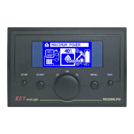
5 – MENU button and choose the parameter, 6 – ESC / output. Figure 1. Front panel of RK-2006LPG controller. Basic operation of the device is to set the preset boiler temperature. In this hands? U need to turn the boiler thermostat knob (4) to set the correct value and confirm it with the OK button (or press the knob). -
Page 5: Overview Of Display Symbols
Overview of display symbols. 1 – Thermostat work indicator, 2 – DHW temperature, 3 – DHW pump work indicator, 4 – Controller work mode, 5 – Boiler water temperature, 6 – Feeder work indicator, 7 – CH pump work indicator, 8 –... -
Page 6: Device Operation Modes
4. Device operation modes. Table 1. Operation mode list. Description Operation mode. STOP Boiler control stopped. Controller maintains central heating and domestic water pump operation, but automatic ignition does not follow. STAND-BY Controller maintains central heating and domestic water pump operation. In case of heat demand automatic ignition of boiler follows. - Page 7 Stabilization of the firing. Boiler burner is switched to the stabilization of the detected flame ignition. While stabilizing the fan runs at a speed the same as when operating in maximum power. Tray gives fuel quantity such as the minimum power. In addition, depending on the service settings fuel dose may be increased gradually.
- Page 8 EXTINCTION (SHUT DOWN). When in this mode the controller turns off the fuel auger and engages the fan to ensure complete fuel combustion and the burner cool down. Fan power when in EXTINCTION (SHUT DOWN) mode is determined by the technician. When EXTINCTION (SHUT DOWN) is finished the controller is switched into CLEANING, STAND-BY or STOP mode, provided EXTINCTION (SHUT DOWN) followed as a result of STOP button pressing.
-
Page 9: Alarms
ALARMS. RK-2006LPG controller continually checks operations of installed devices as well as alarm sensors. In case of failure, the device activates alarm and proper operations are carried out. Information on the problem is also shown on the display. In addition depending on nature of damage the inner sound alarm system may be activated. -
Page 10: Protection Against Overheating And Overheating Of The Boiler
STAND-BY mode. Protection against overheating and overheating of the boiler. RK-2006LPG is protected against overheating of the boiler. If the water temperature reaches a preset value in parameter TEMP service. MAXIMUM THE BOILER, the controller activates the pump absolutely CO. The increase in water temperature in... -
Page 11: Preview And Set User Parameters
Boiler temperature sensor damage. In case of boiler water temperature sensor damage the controller turns off the fan, engages central heating pump, controller switches into STOP mode and activates alarm: CAUTION! This alarm may be cancelled, only if repairs are made. Domestic water temperature sensor damage. -
Page 12: Fuel Type Selection
Burner working mode. (CYCLIC, CONTINUOUS, CONTINUOUS PLUS). 1.1 Fuel type selection. RK-2006LPG controller enables programming ignition settings for four different fuel types. „Fuel type” parameter enables switching between particular settings. Fan, auger and igniter operation are saved for the selected fuel type. -
Page 13: Boiler Operation Max. Power
1.3 Boiler operation max. power. Boiler operation max. power – this parameter enables to limit boiler operation max power. Power limitation is possible thanks to fuel reduction during operation at maximum power. 1.4 CH pump work mode – WINTER/SUMMER – you can turn off the heating du- ring summer by selecting the SUMMER value. -
Page 14: Return Water Temperature
CAUTION! Bacterial flora liquidation option shall be switched on in the night or if water intake does not follow from the domestic water tank, to protect the user against burning. 1.8 Domestic water measured temperature – the controller enables to view the temperature measured in domestic water tank. -
Page 15: Flame Detection Temperature Parameters
Flame detection temperature parameters. These parameters specify operation of the temperature detector of burner fuel ignition. If the system is fitted with optical fire burner detector, parameters change and viewing is unavailable. 1.10 Burner measured temperature – this parameter displays the current measu- red burner temperature. - Page 16 6. Setting the parameters – service mode. Service parameters are divided into groups. For each group are assigned service parameters possible to change. Entry into service mode after press and hold for about 3 seconds the MENU button. regulator displays a list of service parameters possible to edit and change.
- Page 17 4.12 Auger ignition test. 4.13 Auger ignition temperature. 20°C 99°C 5.1 Flame detector type: FD–1, PT–1000, CT–1/2. 5.2 CorrectionFD–1. 5.3 Hysteresis loss of flame (temperature sensor). 1°C 250°C 5.4 Hysteresis loss of flame (optical sensor). 5.5 Flame failure detection delay. 500s 5.6 Fuel ignition timea.
-
Page 18: Language Selection
2. Overall. 2.1 Language selection. RK-2006LPG controller interface offer the function of language selection. Number of availble languages depend on software version being used. 2.2–2.4 Brightness, saturation, contrast of the display. The parameters enable the user to adjust the display to his/her own needs. - Page 19 3.3 Max. fan speed during heating up – this parameter is available, if the function of fan modulation during boiler start is selected. This parameter specifies power of the fan at end of boiler start. 3.4 Ignition modulation start delay – this parameter is available, if the function of fan modulation during boiler start is selected and it describes operation time of the fan with speed according to the selected „Min.
- Page 20 3.8 Fan speed during extinction (shut down) – means fan power during burner extinction (shut down). 3.9 The fan speed for cleaning – this parameter is available only when the cleaning mechanism operates in AUTO mode or COMBI. It specifies that the power of the fan while cleaning the hearth.
-
Page 21: Fuel Auger Operation Parameters
4.x Fuel auger operation parameters. 4.1 Auger filling time – this parameter specifies time required for refilling the main auger with fuel. 4.2 Initial fuel feed – this parameter specifies time, when fuel will be fed before igniter start. Selection of „0s” setting will switch off initial fuel dose feeding. In this case „Fuel dose during ignition”... -
Page 22: Stoker Work Mode
4.5 Fuel feed for max. burner power – this parameter specifies fuel dose fed to the burner during operation with maximum power. The programmed setting specifies feeding time in percent in relation to the time of whole work cycle. 4.6 Fuel feed for min. burner power – this parameter specifies fuel dose fed to the burner during operation with minimum power. -
Page 23: Auger Ignition Test
4.9 Stoker pause time – this parameter specifies pause time during stoker operation when in work cycle. This setting is unavailable if the stoker is switched off or in automatic mode. 4.10 Time to extend the work stoker – this parameter is only available when stker is in automatic mode and determines how long after you turn off the main tray will work stoker. -
Page 24: Ignitor Working Parameters
4.13 Auger ignition temperature – this parameter specifies auger temperature, when the controller activates auger ignition alarm. This parameter is unavailable when „NO” was selected in „Auger ignition test” setting. 5.x Ignitor working parameters. 5.1 Flame detector type – FD–1/ CT–1/2/ PT–1000 – flame detection may follow with two methods: burner temperature measurement or brightness measurement. - Page 25 WARNING! If the hysteresis is larger than the threshold of igniter shut down, flame failure detection procedure is started when the temperature drops or the brightness of the flame to the value of „0”. 5.5 Flame failure detection delay – this parameter specifies how long after the launch procedures for the detection of flame failure or brightness temperature must remain below the hysteresis for the regulator to decide that the furnace was extinguished.
-
Page 26: Cleaning Mechanism
5.12 Smooth stabilization of ignition – setting the parameter to YES will cause the stabilization of firing up the controller gradually increases the amount of fuel fed. This parameter is not available if the parameter STABILIZATION OF FIRING is set to 5.13 Furnace extinction (shut down) time –... - Page 27 ROTO – working mechanism ROTO mode is similar to mode CYCLE. The difference is that the control output cleaning mechanism is attached for the duration of the mode blanked. AUTO – means the cleaning procedure is started automatically after a specified number shut downs or after a sufficient burner operation time.
- Page 28 6.5 Opening time cleaning mechanism – this parameter is only available when cleaning mechanism operates in AUTO mode or ESTATE and determines the time required to complete the opening mechanism during cleaning automatic. 6.6 Closing time cleaning mechanism – This parameter is available only when the cleaning mechanism operates in AUTO mode or COMBI and determines the time it takes to return the mechanism to its rest position after the full opening of the automatic cleaning mechanism.
-
Page 29: Central Heating Pump Work Parameters
6.10 Reversing the cleaning mechanism (default: NO) – setting the parameter to YES results in reversing the exit work of the cleaning mechanism. With the parame- ter on, the power supply is turned on continuously to allow the mechanism exit, and it is turned off during the mechanism operation. -
Page 30: Setting Domestic Water Pump Parameters
8.1 Domestic water path – if „NONE” is selected the domestic water pump is off. In this case temperature sensor input and pump control output may remain disconnected. Selection of „EXISTS” setting provides for interlock release of all parameters and functions related to domestic water path handling. Election of „MIXING PUMP”... -
Page 31: Parameters Of The Mixing Pump
8.5 Domestic water pump extension time – this parameter specifies the time lap- se when domestic water is switched off since the moment when the programmed temperature of domestic water tank was obtained. This setting is available, if dome- stic water path „EXISTS” setting was selected and pump extension was selected. 8.6 The stabilization time after heating hot water –... -
Page 32: Boiler Work Parameters
8.8 Mixing pump work hysteresis – this parameter specifies required return water temperature increase in relation to the mixing pump engagement temperature so that the controller switches off the mixing pump. This parameter is available if domestic water path „MIXING PUMP” setting was selected. 8.9 Heating up the boiler for DHW –... -
Page 33: Burner Power Modulation
The room thermostat. RK-2006LPG was equipped with an input for connecting any room thermostat with contact output. Contacts of the thermostat is signaled by the appearance of the thermometer symbol in the index of the thermostat. - Page 34 9.9 Mode of operation of the room thermostat – this parameter determines the impact of the entry of the room thermostat to the operation of the controller: NORM. – in this mode, the thermostat contacts are closed when the controller starts firing up the burner and the boiler strives to maintain the set temperature of the boiler thermostat knob.
-
Page 35: Data Transmission
CAUTION! If the controller works well for hot water, the burner after contact opening the thermostat can be switched off after a time other than that programmed in the parameter. 10.x Data transmission. 10.1 Data link – the parameter allows the user to select the operation performed by the data connector. -
Page 36: Data Emergency Output - Audible Alarm Or Cleaning Mechanism
10.5 MODBUS access level – defines to what extent the configuration of parameters is available to the ModBus protocol. NONE – no parameters are provided by the controller. READ-OUT – the controller allows you to view its parameters only. USER – changing the user’s parameters only is available (default setting). SERVICE –... -
Page 37: Controller Disassembly
5. Controller disassembly. If controller disassembly is necessary follow the following procedure: – Disconnect the boiler and controller from power supply, – Remove the controller from the boiler, – Disconnect terminals and wires from the controller. 6. Technical Data. Power Supply 230 V ±... - Page 39 DECLARATION OF CONFORMITY Manufacturer:Przedsiębiorstwo Wielobranżowe KEY 11-200 Bartoszyce, ul. Bohaterów Warszawy 67 hereby declares that the product: RK-2006LPG Controller the essential requirements of EC directive on electrical equipment for use within certain voltage limits 2014/35 / UE (LDV) from 02/26/2014...
- Page 40 Manufacturer: Przedsiębiorstwo Wielobranżowe KEY 11-200 Bartoszyce, ul. Bohaterów Warszawy 67 tel. (89) 763 50 50, fax. (89) 763 50 51 www.pwkey.pl e-mail:pwkey@onet.pl...
Need help?
Do you have a question about the RK-2006LPG and is the answer not in the manual?
Questions and answers