
Related Manuals for KEY RK-2006LP


Summary of Contents for KEY RK-2006LP
-
Page 1: Operating Manual
OPERATING MANUAL RK-2006LP AUGER FITTED SOLID FUEL BOILER TEMPERATURE CONTROLLER Version DC19... - Page 3 1. Application. Controller RK-2006LP is designed for temperature control of solid fuel fired water boilers equipped with: - Auger and feeding stoker working with the stoker, - Blow-in fan,, - Ignition glow plug for automatic start, - Central heating pump,...
-
Page 4: Operation
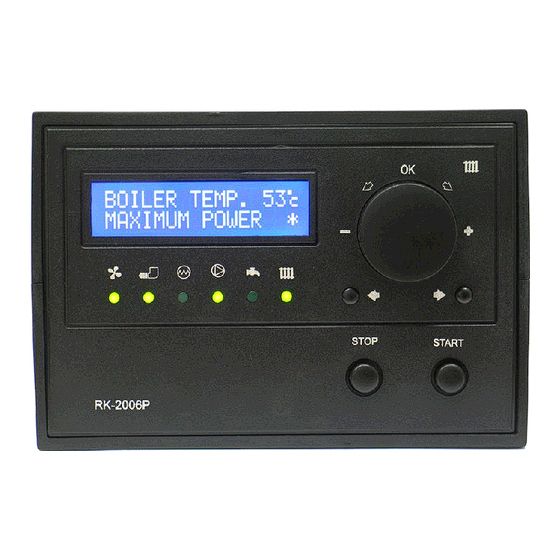
8 - Previous parameter selection button, 9 - STOP button for alarm and settings change cancellation, 10- START button, 11- Next parameter selection button, 12- Boiler thermostat and parameters setting knob with OK confirmation button. Picture 1. Front panel of RK-2006LP controller. - Page 5 3.1. Main window, adjustment mode and devices mode. Following turning on of the controller the main window is displayed. On the top of the display (1) boiler water temperature is shown, and on the bottom operation mode is displayed. Symbol „*” displayed in the right bottom corner indicates burner flame detection.
- Page 6 3.2. Device operation modes. Table 1. Operation mode list. Operation mode Description STOP Boiler control stopped. Controller maintains central heating and domestic water pump operation, but automatic ignition does not follow. STANDBY Controller maintains central heating and domestic water pump operation. In case of heat demand automatic ignition of boiler follows.
- Page 7 mode follows till flame is detected. If the flame is not detected within the specified time, the controller activates „Out of fuel alarm”. Pressing STOP button, exceeding time limit for cleaning, thermostat contacts opening or if water temperature in domestic water tank is obtained during operation in IGNITION mode will result in switching of the controller into the POSTCOMBUSTION mode.
- Page 8 tank is obtained during operation in MINIMUM POWER mode will result in switching of the controller into POSTCOMBUSTION mode. SCAVENGE (AIR PURGING). During the operation with minimum power output, the controller will activate flue scavenge (purging) to ensure removal of accumulated gases. Scavenge (purging) is provided with temporary fan operation in higher speed.
-
Page 9: Emergency Alarm
3.3. ALARMS. RK-2006LP controller continually checks operations of installed devices as well as alarm sensors. In case of failure, the device activates alarm and proper operations are carried out. Information on the problem is also shown on the display. In addition depending on nature of damage the inner sound alarm system may be activated. - Page 10 S E N S O R PROTECTION AGAINST BOILER OVERHEATING. RK-2006LP controller is provided with triple protection against boiler overheating. If boiler water temperature set point is equal to the programmed „Boiler max. temperature” service setting, the controller will engage central heating pump.
- Page 11 DOMESTIC WATER TEMPERATURE SENSOR DAMAGE. If the heating system is fitted with domestic water circuit, in case of sensor damage the controller turns off the domestic water pump and activates alarm: A L A R M : H O T W A T E R T E M P .
- Page 12 Burner work time. Burner start up counter. 4.1. Fuel type selection. RK-2006LP controller enables programming ignition settings for four different fuel types. „Fuel type” parameter enables switching between particular settings. Fan, auger and igniter operation are saved for the selected fuel type.
- Page 13 4.4. Domestic water circuit operation parameters. These parameters specify how the controller ensures domestic water temperature. In case of the system without domestic water circuit, it is not possible for the user to view and change these parameters. Domestic water desired temperature - parameter that specifies temperature of water in domestic water tank that will be obtained by the controller.
- Page 14 4.6. Flame optical detection parameters. These parameters specify operation of burner flame optical detector. If the system is fitted with flame temperature detector, parameters change and viewing is unavailable. The current furnace brightness determined by an optical detector - this parameter displays the current flame brightness measured by the optical detector.
- Page 15 Burner start up counter. Reading of this counter defines start number of the ignition attempts. B U R N E R S T A R T C O U N T 5. Settings – service mode. Holding OK button for 3 seconds enters the service mode where you can review and change the parameters by pressing the selection buttons (8 and 11).
-
Page 16: Language Selection
Outputs test. Service mode end. 5.1. Language selection. RK-2006LP controller interface offer the function of language selection. Number of available languages depend on software version being used. L A N G U A G E E N G L I S H... - Page 17 5.2. Fan operation parameters. Fan modulation during boiler start - selection of „YES” setting means that fan speed modulation will be provided during boiler start. F A N M O D . D U R I N G B O I L E R S T A R T Y E S Min.
- Page 18 Fan speed at min. power - means the fan power when burner of the boiler works with minimum power. F A N S P E E D M I N P O W E R 3 0 % Fan speed during extinction (shut down) - means fan power during burner extinction (shut down).
- Page 19 5.3. Fuel auger operation parameters. Auger filling time - this parameter specifies time required for refilling the main auger with fuel. A U G E R F I L L I N G T I M E 1 0 m i n Initial fuel feed - this parameter specifies time, when fuel will be fed before igniter start.
- Page 20 Stoker work mode - this parameter specifies work mode of the stoker: „OFF” - the burner without the stoker. „CYCL.” - stoker is switched on periodically, regardless of the auger. Work and pause time of the stoker is determined with particular settings. „AUTO”...
- Page 21 A U G E R I G N I T I O N T E S T Y E S CAUTION! In case emergency input is not used, „NO” parameter shall be selected in „Auger ignition test” setting and contacts of „X” input shall be closed. Auger ignition temperature - this parameter specifies auger temperature, when the controller activates auger ignition alarm.
- Page 22 Flame failure detection delay - this parameter specifies how long after the launch procedures for the detection of flame failure or brightness temperature must remain below the hysteresis for the regulator to decide that the furnace was extinguished. F L A M E V A N I S H D E L A Y 6 0 s...
- Page 23 Furnace extinction (shut down) time - if the controller switches to extinction (shut down) mode, the induction fan is activated according to power selected in „Fan speed at extinction (shut down)” setting. The parameter defines the duration of extinction. This function ensures combustion of all fuel remains and burner cool down.
- Page 24 H E A R T H C L E A N I N G A U T O Cleaning mechanism work time - the parameter is available only when the cleaning mechanism operates in the CYCLE, ROTO or COMBI mode. It defines the duration the cleaning mechanism is activated when the burner is turned on.
- Page 25 Minimum operating time without cleaning - the parameter is available only when the cleaning mechanism operates in the AUTO or COMBI mode. It specifies the minimum number of hours the burner must operate so that the cleaning could be activated. If the minimum operation time is not reached, the cleaning will not be started even if the required number of shutdowns has occurred.
- Page 26 5.6. Setting domestic water pump parameters. The controller offers an additional function for heating of domestic water. Not every heating system is provided with domestic water tank and charge pump, this circuit may be switched off or used for control of the pump that mixes the return water in the boiler.
- Page 27 Domestic water pump extension time - this parameter specifies the time lapse when domestic water is switched off since the moment when the programmed temperature of domestic water tank was obtained. This setting is available, if domestic water path „EXISTS” setting was selected and pump extension was selected.
- Page 28 5.7. Boiler work parameters. Minimum boiler temperature - this parameter specifies boiler temperature when the controller shall switch off central heating and domestic water pumps. It is the lowest temperature setting of the boiler that can be programmed with thermostat’s knob.
- Page 29 F A C T O R 5.8. Room thermostat. RK-2006LP controller has been equipped with the input enabling connection of any room thermostat provided with contact output. Closing the thermostat contacts is signalized with blinking its lamp. When the contacts are opened, the lamp will be off.
- Page 30 Time constant of adaptation – the parameter is available when the thermostat is in the mode of adaptation. It defines the rate of „searching' the appropriate boiler programmed temperature by the algorithm of adaptation. The value of parameter should be selected experimentally depending on the properties of the heated object. When frequent room overheating occurs during the work of the algorithm of adaptation and frequent changes in the outside conditions –...
-
Page 31: Technical Data
5.11. Service mode exit. By choosing this option and confirmation with OK button you can exit service mode. The controller also exits the service mode, if no button is pressed after 60 seconds. – – E X I T – – 6. - Page 32 Figure 2. RK-2006LP Controller connection diagram.
- Page 33 9. Notes. Settings. Light Parameter Thermostat Boiler max. power. Domestic water desired temperature. HTW pump Domestic water heating priority. Brightness when fuel ignition has occurred (FD-1). Igniter Burner temperature with fuel ignited (PT-1000, CT-1/2).
- Page 34 Settings Light Parameter Fan modulation during boiler start. Min. fan speed during heating up. Max. fan speed during heating up. Ignition modulation start delay. Fan speed during ignition. Fan speed at max. power. Fan speed at min. power. Fan speed at extinction. Fan speed during cleaning mode.
- Page 35 Settings Light Parameter Kindle fire stabilize time. Smooth kindle fire stabilize. Furnace extinction time. Furnace cleaning mode. Cleaning mechanism work time. Cleaning mechanism retraction time. Igniter Cleaning mechanism pause time. Cleaning mechanism opening time. Cleaning mechanism closing time. Number shut downs before cleaning. Minimum operating time without cleaning.
-
Page 39: Declaration Of Conformity
DECLARATION OF CONFORMITY Manufacturer: Przedsiębiorstwo Wielobranżowe KEY 11-200 Bartoszyce, ul. Bohaterów Warszawy 67 hereby declares that the product: RK-2006 Controller is in conformity with provisions of the following directives: 73/23/EWG i 93/68/EWG (LVD 73/23/EEC + 93/68/EEC), as superseded by Directive 2006/95/WE (EC Directive 2006/95/EEC);... - Page 40 Manufacturer: Przedsiębiorstwo Wielobranżowe KEY 11-200 Bartoszyce, ul. Bohaterów Warszawy 67 tel. (89) 763 50 50, fax. (89) 763 50 51 www.pwkey.pl e-mail:pwkey@onet.pl...
Need help?
Do you have a question about the RK-2006LP and is the answer not in the manual?
Questions and answers