
Subscribe to Our Youtube Channel
Related Manuals for KEY RK-2006SPGM+MZL


Summary of Contents for KEY RK-2006SPGM+MZL
- Page 1 OPERATION MANUAL RK-2006SPGM +MZL Pellet fuel burner fitted boiler temperature controller. Version 5701...
-
Page 2: Table Of Contents
Table of Contents. Introduction ......................3 Operation ......................4 Overview of display symbols ................Device operation modes ..................6 Table 1. Operation mode list ................6 Alarms ......................... Protection against overheating and overheating of the boiler ......10 Preview and set user parameters ................ 11 Table 2. - Page 3 1. Application. Controller RK-2006SPGM is designed for temperature control of solid fuel fired water boilers equipped with: – Auger and feeding stoker working with the stoker, – Blow-in fan, – Ignition glow plug for automatic start, – Central heating pump, –...
-
Page 4: Operation
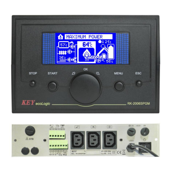
3. Operation. After power-up the controller displays the name and version of the software, then goes to the state it was in before shutting down or lose power. On the front panel of the controller (Figure ) there is: 1 – display, 2 –... - Page 5 Description of display symbols. 1 – Thermostat work indicator, 2 – DHW temperature, 3 – DHW pump work indicator, 4 – Controller work mode, 5 – Boiler water temperature, 6 – Feeder work indicator, 7 – The outdoor temperature, 8 – CH pump work indicator, 9 –...
-
Page 6: Device Operation Modes
4. Device operation modes. Table 1. Operation mode list. Description Operation mode. STOP Boiler control stopped. Controller maintains central heating and domestic water pump operation, but automatic ignition does not follow. STAND-BY Controller maintains central heating and domestic water pump operation. In case of heat demand automatic ignition of boiler follows. - Page 7 mode follows till flame is detected. If the flame is not detected within the specified time, the controller activates „Out of fuel alarm”. Pressing STOP button, exceeding time limit for cleaning, thermostat contacts opening or if water temperature in domestic water tank is obtained during operation in IGNITION mode will result in switching of the controller into EXTINCTION (SHUT DOWN) mode.
- Page 8 SCAVENGE (AIR PURGING). During the operation with minimum power output, the controller will activate flue sca- venge (purging) to ensure removal of accumulated gases. Scavenge (purging) is provided with temporary fan operation in higher speed. EXTINCTION (SHUT DOWN). When in this mode the controller turns off the fuel auger and engages the fan to en- sure complete fuel combustion and the burner cool down.
-
Page 9: Alarms
ALARMS. RK-2006SPGM controller continually checks operations of installed devices as well as alarm sensors. In case of failure, the device activates alarm and proper opera- tions are carried out. Information on the problem is also shown on the display. In addition depending on nature of damage the inner sound alarm system may be activated. -
Page 10: Protection Against Overheating And Overheating Of The Boiler
CAUTION! This alarm may be cancelled only if the auger temperature drops below set point. If the alarm was cancelled before extinction completion, only sound alarm will be turned off. Auger sensor damage. In case of auger temperature sensor damage, as in case of overheating, the control- ler will go to shut down mode and will activate the appropriate alarm: CAUTION! This alarm may be cancelled only after repairs. -
Page 11: Preview And Set User Parameters
Domestic water temperature sensor damage. If the heating system is fitted with domestic water circuit, in case of sensor damage the controller turns off the domestic water pump and activates alarm: CAUTION! This alarm does not require cancellation. The alarm is deactivatedauto- matically, if repairs are made. -
Page 12: Boiler Operation Max. Power
1.13 Current furnace brightness (FD–1). 1.14 Ignitor turn-off depending on the illuminance value. 1.15 Burner running time. 1.16 Number of inflammation burner. 1.17 Boiler is turned on. 1.18 DHW heating is turned on. 1.19 Alarms cancellation. 1.20 Burner working mode. (CONTINUOUS), CYCLIC) 1.21 SUMMER threshold temperature. -
Page 13: Return Water Temperature
1.5 Domestic water desired temperature – parameter that specifies temperature of water in domestic water tank that will be obtained by the controller. 1.6 Domestic water heating priority – this parameter specifies operation of central heating and domestic water pumps during hot water preheating. When priority is selected during operation and hot water preheating, the controller engages domestic water pump and switches off central heating pump. -
Page 14: Flame Optical Detection Parameters
Flame detection temperature parameters. These parameters specify operation of the temperature detector of burner fuel ignition. If the system is fitted with optical fire burner detector, parameters change and viewing is unavailable. 1.10 Burner measured temperature – this parameter displays the current measured burner temperature. -
Page 15: Alarms Cancellation
1.16 Burner start up counter – reading of this counter defines start number of the ignition attempts. 1.17 Boiler on - the parameter informs the user if the boiler is turned on and allows him/her to turn it on or off. 1.18 DHW heating on –... -
Page 16: Setting The Parameters - Service Mode
1.23 Increasing the temperature of the boiler – this parameter allows you to adjust the characteristics of a weather cycle 1 to cycle 2. 1.24 Heating circuit 2 – This parameter enables the activation and operation mode selection circuit 2. YES –... -
Page 17: Service Settings
Table 3. Table service parameter F – parameter depends on the type of fuel. Parametr 2.1 Language. (see description). 2.2 Brightness of the display. 2.3 Saturation. Overall 2.4 Contrast. 2.5 Service settings. 2.7 Output testing. 3.1 Fan modulation during boiler start. 3.2 Min. - Page 18 6.6 Closing time cleaning mechanism. 900s 6.7 Number shut downs before cleaning. 6.8 Minimum operating time without cleaning. max–1h F 6.9 Maximum working time without cleaning. min+1h 7.1 Central heating pump work mode: TERM, AUTO. 7.2 Central heating pump periodic work. CH pump 7.3 Central heating pump periodic work time.
-
Page 19: Testing Out
2.x Overall. 2.1 Language selection – RK-2006SPGM controller interface offer the function of language selection. Number of available languages depend on software version being used. 2.2–2.4 Brightness, saturation, contrast of the display – the parameters enable the user to adjust the display to his/her own needs. 2.5 Service settings –... - Page 20 3.3 Max. fan speed during heating up – this parameter is available, if the function of fan modulation during boiler start is selected. This parameter specifies power of the fan at end of boiler start. 3.4 Ignition modulation start delay – this parameter is available, if the function of fan modulation during boiler start is selected and it describes operation time of the fan with speed according to the selected „Min.
-
Page 21: Fuel Auger Operation Parameters
3.9 The fan speed for cleaning – this parameter is available only when the cleaning mechanism operates in AUTO mode or COMBI. It specifies that the power of the fan while cleaning the hearth. 3.10 Fan scavenge (air purging) – the controller offers the function of scavenge (air purging), which simply includes periodical switching on of the fan during burner operation for the purpose of removal of accumulated gases. - Page 22 4.2 Initial fuel feed – this parameter specifies time, when fuel will be fed before igniter start. Selection of „0s” setting will switch off initial fuel dose feeding. In this ca- se „Fuel dose during ignition” setting shall be programmed as the value over „0%”. 4.3 Fuel feed cycle –...
-
Page 23: Stoker Work Mode
4.7 Stoker work mode – This parameter defines the operation of the internal tray (stoker): OFF – the burner without the stoker. CYCL – stoker is switched on periodically, regardless of the auger. Work and pause time of the stoker is determined with particular settings. AUTO –... -
Page 24: Ignitor Working Parameters
4.11 Stoker emptying time – this parameter specifies time needed for removal of the whole fuel from the stoker. Stoker emptying during extinguishing of feeder, feeding initial fuel dose (portion), and during burner shut down. This setting is unavailable if the stoker is switched off. 4.12 Auger ignition test –... - Page 25 5.2 Indication correction of flame optical detector – only when flame optical detector (FD-1) is on. Describes light intensity detected by optical detector when burner is off. The correction value is deducted from the value light intensity during the flame detection. Correction allows calibration of FD-1 sensor the way that during burner shut down value (no flame) of the light equals zero.
- Page 26 5.8 Test the temperature of the fuel shortage – This parameter determines the temperature to which must reduce the boiler water temperature to the regulator be- gan testing the fuel shortage. 5.9 Fuel shortage testing time – parametr ten określa, przez ile czasu od rozpo- częcia testowania braku opału temperatura wody w kotle musi być...
-
Page 27: Cleaning Mechanism
6.x Cleaning mechanism. 6.1 Furnace cleaning mode – this parameter specifies the way the cleaning mechanism works: NONE – means that the burner does not have a cleaning mechanism. In this case, the output DATA is working as an external alarm. CYCL –... - Page 28 COMBI 2 – a mode similar to COMBI; the difference is that when the clearing device is turned on, the blower always operates with the capacity programmed in the para- meter BLOWER SPEED RATE AT CLEANING, regardless of the current stage of operations (except emergencies).
-
Page 29: Central Heating Pump Work Parameters
6.7 Number of extinctions before cleaning – this parameter is available only when the cleaning mechanism operates in AUTO mode or COMBI and determines which in turn goes off to start the procedure of cleaning. 6.8 Minimum operating time without cleaning – this parameter is available only when the cleaning mechanism operates in AUTO or COMBI mode. -
Page 30: Setting Domestic Water Pump Parameters
7.3 CH pump periodic work time – this parameter is available, if CH pump works in „THERMOSTAT” mode and the function of CH pump periodic work is active. The programmed setting will specify the time lapse between CH pump work, in case of opened contacts of the room thermostat. - Page 31 8.4 Domestic water pump work extension – quick switching off of the pump refilling domestic water tank may result in excessive rise of boiler temperature. This parameter enables switching on of domestic water pump extension. This setting is available, if domestic water path „EXISTS” setting was selected. 8.5 Domestic water pump extension time –...
-
Page 32: Boiler Work Parameters
9.x Boiler work parameters. 9.1 Minimum boiler temperature – this parameter specifies boiler temperature when the controller shall switch off central heating and domestic water pumps. It is the lowest temperature setting of the boiler that can be programmed with thermostat’s knob. -
Page 33: Burner Power Modulation
9.6 Boiler overheating temperature – this parameter specifies boiler water temperature when the controller switches off control and activates boiler overheating alarm. 9.7 Burner power modulation – when modulation is switched on it will results in gradual reduction of fan speed and fuel dose to obtain boiler water temperature corresponding to the programmed setting. - Page 34 CAUTION! In the case of not using the room thermostat input should remain closed, and the operation of the thermostat set to the NORM .. In this case, the boiler will operate continuously maintaining the set temperature of the boiler thermostat knob. 9.10 The time constant of adaptation –...
-
Page 35: Data Transmission
10.x Data transmission. 10.1 Data link – the parameter allows the user to select the operation performed by the data connector. NONE – connector inactive (default value). MODBUS RTU – Communication by RS-485 bus with using the ModBus standard RTU protocol. 10.2 MODBUS device number –... - Page 36 10.5 MODBUS access level – defines to what extent the configuration of parameters is available to the ModBus protocol. NONE – no parameters are provided by the controller. READ-OUT – the controller allows you to view its parameters only. USER – changing the user’s parameters only is available (default setting). SERVICE –...
-
Page 37: Circuit 2
13.x Circuit 2. 13.1 Circulation mode 2 – This parameter allows you to attach the second circuit, and choose whether this mode is to be operated stirrer with a pump or the pump itself. 13.2 Mode switching circuit 2 – when working in a mixing valve pump: TERM –... - Page 38 13.5 Lowering the thermostat –in the case of opening the contacts of thermostat temperature the second circuit is reduced by the value set in this parameter. 13.6 Increasing the temperature of the boiler – circulation set temperature + the value of raising the temperature of the boiler - this is the minimum boiler temperature that will be set on the boiler.
-
Page 39: The Heating Curve
13.11 Actuator pause time – ctime between starts of the actuator during a slow opening or closing the valve. 13.12 The transit time of the actuator – the time required to complete the actuator to go from open to close or vice versa. 14.x The heating curve 14.1 Outside temperature sensor if the system is equipped with an external... -
Page 40: Controller Disassembly
7. Controller disassembly. If controller disassembly is necessary follow the following procedure: – Disconnect the boiler and controller from power supply, – Remove the controller from the boiler, – Disconnect terminals and wires from the controller. 8. Technical Data. Power Supply 230 V ±... - Page 41 Figure 2. RK-2006SPGM+MZL Controller connection diagram.
- Page 42 Figure 2. RK-2006SPGM+MZL Controller connection diagram.
- Page 43 DECLARATION OF CONFORMITY Manufacturer:Przedsiębiorstwo Wielobranżowe KEY 11-200 Bartoszyce, ul. Bohaterów Warszawy 67 hereby declares that the product: RK-2006SPGMController is in conformity with provisions of the following directives: 73/23/EWG i 93/68/EWG (LVD 73/23/EEC + 93/68/EEC), as superseded by Directive 2006/95/WE (EC Directive 2006/95/EEC);...
- Page 44 Manufacturer: P.W. KEY 11-200 Bartoszyce, ul. Bohaterów Warszawy 67 tel. (89) 763 50 50, fax. (89) 763 50 51 www.pwkey.pl e-mail: pwkey@onet.pl...
Need help?
Do you have a question about the RK-2006SPGM+MZL and is the answer not in the manual?
Questions and answers