
Subscribe to Our Youtube Channel
Related Manuals for KEY RK-2006LSPz


Summary of Contents for KEY RK-2006LSPz
- Page 1 OPERATION MANUAL RK-2006LSPz AUGER FITTED SOLID FUEL BOILER TEMPERATURE CONTROLLER Version C820...
- Page 3 1. Application. Controller RK-2006LSP is designed for temperature control of solid fuel fired water boilers equipped with:: - Auger and feeding stoker working with the stoker, - Blow-in fan, - Ignition glow plug for automatic start, - Central heating pump, - Hot tap water pump or mixing pump (option), - Alarm indicator or or ash removal system (option), - Room thermostat (option).
-
Page 4: Operation
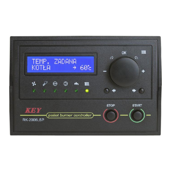
3. Operation. After turning the controller on, the name and software version is displayed and all signal lamps are on to enable checking of functionalities. When the controller is turn on it will return to its last state before turning off or power failure. On the front panel of the controller (Figure 1) there is: 1 - Display, 2 - Fan indicator,... - Page 5 3.1. Main window, adjustment mode and devices mode. Following turning on of the controller the main window is displayed. On the top of the display (1) boiler water temperature is shown, and on the bottom operation mode is displayed. Symbol „*” displayed in the right bottom corner indicates burner flame detection.
- Page 6 STOP. Controller maintains central heating and domestic water pumps operation only to protect the boiler against overheating and auger channel ignition. Room thermostat contacts closing(call for heat) and domestic water temperature drop do not result in any action. Pressing START button (10) will result in switching the controller to STAND-BY mode.
- Page 7 MINIMUM POWER OPERATION MODE. When in this mode the controller operates fuel feeding and fan operation to maintain firing to ensure the minimum fuel consumption. Fuel and air feeding rate is adjusted by the technician. If in spite of boiler minimum power, increase temperature follows of water temperature in relation to the top hysteresis parameter setting, the controller will be switched into EXTINCTION(SHUT DOWN) mode.
- Page 8 3.3. ALARMS. RK-2006LSP controller continually checks operations of installed devices as well as alarm sensors. In case of failure, the device activates alarm and proper operations are carried out. Information on the problem is also shown on the display. In addition depending on nature of damage the inner sound alarm system may be activated.
- Page 9 Auger sensor damage. In case of auger temperature sensor damage, as in case of overheating, the controller will go to shut down mode and will activate the appropriate alarm: A L A R M : A U G E R T E M P .
- Page 10 Domestic water temperature sensor damage. If the heating system is fitted with domestic water circuit, in case of sensor damage the controller turns off the domestic water pump and activates alarm: A L A R M : H O T W A T E R T E M P .
-
Page 11: Fuel Type Selection
Table 2. User settings list. Light Parameter Min. Max. Auger Fuel type. Desired boiler temperature. 40°C 90°C Thermostat Boiler max. power. 100% CH pump Central heating pump operation mode. WINTER SUMMER Domestic water desired temperature. 30°C 60°C Domestic water heating priority. pump Domestic water tank bacterial flora liquidation program. - Page 12 4.4. Domestic water circuit operation parameters. These parameters specify how the controller ensures domestic water temperature. In case of the system without domestic water circuit, it is not possible for the user to view and change these parameters. Domestic water desired temperature - parameter that specifies temperature of water in domestic water tank that will be obtained by the controller.
- Page 13 4.6. Flame optical detection parameters. These parameters specify operation of burner flame optical detector. If the system is fitted with flame temperature detector, parameters change and viewing is unavailable. The current furnace brightness determined by an optical detector - this parameter displays the current flame brightness measured by the optical detector.
- Page 14 Burner start up counter. Reading of this counter defines start number of the ignition attempts. B U R N E R S T A R T C O U N T 5. Settings – service mode. Holding OK button for 3 seconds enters the service mode where you can review and change the parameters by pressing the selection buttons (8 and 11).
-
Page 15: Language Selection
Hysteresis loss of flame (temperature sensor). 1°C 250°C Flame failure detection delay. 500s Fuel ignition time. 1min 15min Ignition try count. Furnace extinction time. 1min 30min Furnace cleaning mode (See description). Igniter Cleaning mechanism work time. 900s Cleaning mechanism retraction time. 900s Cleaning mechanism pause time. - Page 16 M I N . F A N S P E E D H E A T I N G Max. fan speed during heating up - this parameter is available, if the function of fan modulation during boiler start is selected. This parameter specifies power of the fan at end of boiler start.
- Page 17 Fan speed during cleaning mode - only when AUTO is on. F A N S P E E D D U R I N G C L E A N I N G 1 0 0 % Fan scavenge (air purging) - the controller offers the function of scavenge (air purging), which simply includes periodical switching on of the fan during burner operation for the purpose of removal of accumulated gases.
- Page 18 Fuel feed cycle - auger operation cycle includes fuel feeding and feeding pause. This parameter specifies the time of the whole cycle. The desired value specifies all burner work modes which require fuel feeding (ignition, maximum and minimum power). F U E L F E E D C Y C L E 1 5 s...
- Page 19 Stoker pause time - this parameter specifies pause time during stoker operation when in work cycle. This setting is unavailable if the stoker is switched off or in automatic mode. S T O K E R P A U S E T I M E Stoker extra work time - this parameter is available only, when the stoker works in automatic mode and it specifies stoker work time after auger switching off.
- Page 20 5.4. Fuel ignition, extinction (shut down) and cleaning combustion chamber. Flame detector - flame detection may follow with two methods: burner temperature measurement or brightness measurement. In case when temperature sensor is used, depending on its location, temperature measurement range may be from several degrees to several hundred degrees.
- Page 21 F U E L I G N I T I O N T I M E 3 m i n Ignition try count - this parameter specifies how many times ignition may fail until the controller activates „Out of fuel alarm” and switches into STOP mode. The alarm is indicated with adequate message displayed on the display.
- Page 22 Cleaning mechanism retraction time - this parameter is available only when the cleaning mechanism is activated (AUTO mode, or CYCLE). It specifies the time required for the mechanism retraction to the rest position after turning off the control output. M E C H A N I S M R E T U R N T I M E 1 2 0 s...
- Page 23 P U M P W O R K M O D E A U T O Central heating (CH) pump periodic switching on - this parameter enables periodic operation of central heating pump and water transfer in the heating circuit. The pump is activated periodically every 30 seconds according to selected time in „CH pump periodic work”...
- Page 24 Increase temperature during domestic water heating - Closing thermostat contacts means that boiler operation will follow according to the temperature programmed with the thermostat knob. If domestic water tank heating is necessary, the desired boiler temperature is higher in relation to the desired domestic water by the selected value in this setting.
- Page 25 5.7. Boiler work parameters. Minimum boiler temperature - this parameter specifies boiler temperature when the controller shall switch off central heating and domestic water pumps. It is the lowest temperature setting of the boiler that can be programmed with thermostat’s knob.
- Page 26 Burner power modulation - when modulation is switched on it will results in gradual reduction of fan speed and fuel dose to obtain boiler water temperature corresponding to the programmed setting. B U R N E R P O W E R M O D U L A T I O N Y E S Burner power modulation factor - this parameter specifies degree setting when...
-
Page 27: Room Thermostat
6. Room thermostat. RK-2006LSP controller is fitted with the input that enables connection of any room thermostat provided with contact output. If room temperature is lower from the required one (closed contacts) light on the room thermostat will be switched on. This means that the boiler will maintain the setting programmed with knob. - Page 28 Figure 2. RK-2006LSP Controller connection diagram.
- Page 29 10. Notes. Settings. Light Parameter Thermostat Boiler max. power. Domestic water desired temperature. HTW pump Domestic water heating priority. Brightness when fuel ignition has occurred (FD-1). Igniter Burner temperature with fuel ignited (PT-1000, CT-1/2).
- Page 30 Settings Light Parameter Fan modulation during boiler start. Min. fan speed during heating up. Max. fan speed during heating up. Ignition modulation start delay. Fan speed during ignition. Fan speed at max. power. Fan speed at min. power. Fan speed at extinction. Fan speed during cleaning mode.
- Page 31 Settings Light Parameter Hysteresis loss of flame (temperature sensor). Flame failure detection delay. Fuel ignition time. Ignition try count. Furnace extinction time. Furnace cleaning mode. Igniter Cleaning mechanism work time. Cleaning mechanism retraction time. Cleaning mechanism pause time. Number shut downs before cleaning. Minimum operating time without cleaning.
-
Page 35: Declaration Of Conformity
DECLARATION OF CONFORMITY Manufacturer: Przedsiębiorstwo Wielobranżowe KEY 11-200 Bartoszyce, ul. Bohaterów Warszawy 67 hereby declares that the product: RK-2006 Controller is in conformity with provisions of the following directives: 73/23/EWG i 93/68/EWG (LVD 73/23/EEC + 93/68/EEC), as superseded by Directive 2006/95/WE (EC Directive 2006/95/EEC);... - Page 36 Manufacturer: Przedsiębiorstwo Wielobranżowe KEY 11-200 Bartoszyce, ul. Bohaterów Warszawy 67 tel. (89) 763 50 50, fax. (89) 763 50 51 www.pwkey.pl e-mail:pwkey@onet.pl...
Need help?
Do you have a question about the RK-2006LSPz and is the answer not in the manual?
Questions and answers