Advertisement
Quick Links
Advertisement

Subscribe to Our Youtube Channel
Related Manuals for KEY RK-2006LPG2


Summary of Contents for KEY RK-2006LPG2
- Page 1 OPERATION MANUAL RK-2006LPG2 Pellet fuel burner fitted boiler temperature controller. Wersja 4B00...
- Page 3 1. Application. Controller RK-2006LPG2 is designed for temperature control of solid fuel fired water boilers equipped with: - Auger and feeding stoker working with the stoker, - Blow-in fan, - Ignition glow plug for automatic start, - Central heating pump,...
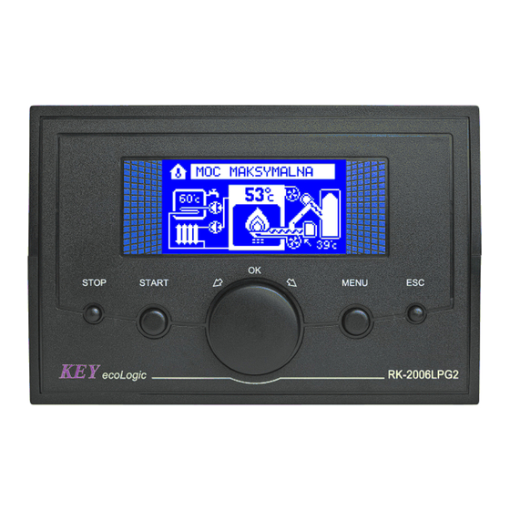
- Page 4 5 – MENU button and choose the parameter, 6 – ESC / output. Figure 1. Front panel of RK-2006LPG2 controller. Basic operation of the device is to set the preset boiler temperature. In this hands? U need to turn the boiler thermostat knob (4) to set the correct value and confirm it with the OK button (or press the knob).
- Page 5 Overview of display symbols. 1 – Thermostat work indicator, 2 – DHW temperature, 3 – DHW pump work indicator, 4 – Controller work mode, 5 – Boiler water temperature, 6 – Additional fan, 7 – Feeder work indicator, 8 – CH pump work indicator, 9 –...
-
Page 6: Standby Mode
4. Device operation modes. Table 1. Operation mode list. Description Operation mode. STOP Boiler control stopped. Controller maintains central heating and domestic water pump operation, but automatic ignition does not follow. STAND-BY Controller maintains central heating and domestic water pump operation. In case of heat demand automatic ignition of boiler follows. - Page 7 mode follows till flame is detected. If the flame is not detected within the specified time, the controller activates „Out of fuel alarm”. Pressing STOP button, exceeding time limit for cleaning, thermostat contacts opening or if water temperature in domestic water tank is obtained during operation in IGNITION mode will result in switching of the controller into EXTINCTION (SHUT DOWN) mode.
- Page 8 SCAVENGE (AIR PURGING). During the operation with minimum power output, the controller will activate flue scavenge (purging) to ensure removal of accumulated gases. Scavenge (purging) is provided with temporary fan operation in higher speed. EXTINCTION (SHUT DOWN). When in this mode the controller turns off the fuel auger and engages the fan to ensure complete fuel combustion and the burner cool down.
- Page 9 ALARMS. RK-2006LPG2 controller continually checks operations of installed devices as well as alarm sensors. In case of failure, the device activates alarm and proper operations are carried out. Information on the problem is also shown on the display. In addition depending on nature of damage the inner sound alarm system may be activated.
- Page 10 CAUTION! This alarm may be cancelled only if the auger temperature drops below set point. If the alarm was cancelled before extinction completion, only sound alarm will be turned off. Auger sensor damage. In case of auger temperature sensor damage, as in case of overheating, the controller will go to shut down mode and will activate the appropriate alarm: CAUTION! This alarm may be cancelled only after repairs.
- Page 11 Boiler temperature sensor damage. In case of boiler water temperature sensor damage the controller turns off the fan, engages central heating pump, controller switches into STOP mode and activates alarm: CAUTION! This alarm may be cancelled, only if repairs are made. Domestic water temperature sensor damage.
- Page 12 The user can switch between different parameters by turning the knob (4). By pressing the knob you enter the mode of change of the selected parameter – the parameter will be backlit. You can change the value of the selected parameter by turning the knob. To confirm the change press the knob again, and the controller will return to the list of parameters.
- Page 13 CAUTION! Fuel type may be changed, if the controller is in STOP mode only. Desired boiler temperature – it is the temperature setting that will be obtained by the controller, if room thermostat input contacts are closed. 1.3 Boiler operation max. power. Boiler operation max.
- Page 14 1.7 Bacterial flora liquidation in domestic water tank – the controller enables manual activation of program for bacterial flora liquidation in domestic water tank. When „YES” is selected, it activates the process of heating the domestic water tank above 75°C. When the required temperature is obtained the controller switches off the bacterial flora liquidation program automatically.
- Page 15 1.14 Brightness when fuel ignition has occurred – if the optical detector reading will be equal or higher than this desired setting, the controller will switch off the igniter and assume that ignition has occurred. Flame detection temperature parameters. These parameters specify operation of the temperature detector of burner fuel ignition.
- Page 16 1.18 DHW heating on. The parameter informs the user if the DHW heating is turned on and allows him/her to turn it on or off. 1.19 Alarms cancellation. The parameter enables the user to cancel the alarms recorded in the controller data storage.
- Page 17 Table 3. Table service parameter. Parametr 2.1 Language. (see description)). 2.2 Brightness of the display. 2.3Saturation. Overall 2.4 Contrast. 2.5 Service settings. 2.7 Output testing. 3.1 Fan modulation during boiler start. 3.2 Min. fan speed during heating up. 100% 3.3 Max. fan speed during heating up. 100% 3.4 Ignition modulation start delay.
- Page 18 6.8 Minimum operating time without cleaning. max–1h 6.9 Maximum working time without cleaning. min+1h 7.1 Central heating pump work mode: TERM, AUTO. 7.2 Central heating pump periodic work. CH pump 7.3 Central heating pump periodic work time. 1min 99min 8.1 Domestic water path: OFF, ON, MIXING PUMP, 8.2 Domestic water heating hysteresis.
- Page 19 2.x Overall. 2.1 Language selection. RK-2006LPG2 controller interface offer the function of language selection. Number of available languages depend on software version being used. 2.2–2.4 Brightness, saturation, contrast of the display. The parameters enable the user to adjust the display to his/her own needs.
- Page 20 3.x Fan operation parameters. 3.1 Fan modulation during boiler start – selection of „YES” setting means that fan speed modulation will be provided during boiler start. 3.2 Min. fan speed during heating up – this parameter is available, if the function of fan modulation during boiler start is selected.
- Page 21 3.6 Fan speed at max. power – means the fan power when burner of the boiler works with maximum power. 3.7 Fan speed at min. power – means the fan power when burner of the boiler works with minimum power. 3.8 Fan speed during extinction (shut down) –...
- Page 22 3.12 Fan scavenge (air purging) pause time – this parameter specifies pause time during scavenge. This setting is unavailable if „Fan scavenge” (air purging) setting was not selected. 3.13 Fan speed during scavenge (air purging) – this parameter specifies fan power during scavenge (air purging).
- Page 23 4.4 Fuel feed during ignition – this parameter specifies fuel dose that is fed to the burner during lighter operation. The programmed setting specifies feeding time in percent in relation to the time of whole work cycle. Selection of „0s” setting will switch fuel feeding during operation of the lighter.
- Page 24 4.8 Stoker work time – this parameter specifies operation time of the stoker in whole work cycle. This setting is unavailable if the stoker is switched off or in automatic mode. 4.9 Stoker pause time – this parameter specifies pause time during stoker operation when in work cycle.
- Page 25 CAUTION! In case emergency input is not used, „NO” parameter shall be selected in „Auger ignition test” setting and contacts of „X” input shall be closed. 4.13 Auger ignition temperature – this parameter specifies auger temperature, when the controller activates auger ignition alarm. This parameter is unavailable when „NO”...
- Page 26 WARNING! If the hysteresis is larger than the threshold of igniter shut down, flame failure detection procedure is started when the temperature drops or the brightness of the flame to the value of „0”. 5.5 Flame failure detection delay – this parameter specifies how long after the launch procedures for the detection of flame failure or brightness temperature must remain below the hysteresis for the regulator to decide that the furnace was extinguished.
- Page 27 5.12 Smooth stabilization of ignition – setting the parameter to YES will cause the stabilization of firing up the controller gradually increases the amount of fuel fed. This parameter is not available if the parameter STABILIZATION OF FIRING is set to 5.13 Furnace extinction (shut down) time –...
- Page 28 6.x Cleaning mechanism. 6.1 Furnace cleaning mode – this parameter specifies the way the cleaning mechanism works: NONE – means that the burner does not have a cleaning mechanism. In this case, the output DATA is working as an external alarm. CYCL –...
- Page 29 COMBI 2 – a mode similar to COMBI; the difference is that when the clearing device is turned on, the blower always operates with the capacity programmed in the para- meter BLOWER SPEED RATE AT CLEANING, regardless of the current stage of operations (except emergencies).
- Page 30 6.7 Number of extinctions before cleaning – this parameter is available only when the cleaning mechanism operates in AUTO mode or COMBI and determines which in turn goes off to start the procedure of cleaning. 6.8 Minimum operating time without cleaning – this parameter is available only when the cleaning mechanism operates in AUTO or COMBI mode.
- Page 31 7.3 CH pump periodic work time – this parameter is available, if CH pump works in „THERMOSTAT” mode and the function of CH pump periodic work is active. The programmed setting will specify the time lapse between CH pump work, in case of opened contacts of the room thermostat.
- Page 32 8.3 Increase temperature during domestic water heating – Closing thermostat contacts means that boiler operation will follow according to the temperature programmed with the thermostat knob. If domestic water tank heating is necessary, the desired boiler temperature is higher in relation to the desired domestic water by the selected value in this setting.
- Page 33 CAUTION! This feature does not work if water preparation is done without priority or the controller is in summer mode. 8.7 Mixing pump engaging temperature – this parameter specifies required return water temperature so that the mixing pump engagement follows the controller. This parameter is available if domestic water path „MIXING PUMP”...
- Page 34 9.4 Burner power switching hysteresis – when the programmed boiler water temperature is obtained the controller is switched to minimum power work mode. This parameter specifies required water temperature drop so that maximum power work mode was activated. After switching to maximum power the fuel and air feeding dose is determined according to burner power modulation.
- Page 35 The room thermostat. RK-2006LPG2 was equipped with an input for connecting any room thermostat with contact output. Contacts of the thermostat is signaled by the appearance of the thermometer symbol in the index of the thermostat. CAUTION! The entrance of the room thermostat is active only during WINTER.
- Page 36 CAUTION! If the controller works well for hot water, the burner after contact opening the thermostat can be switched off after a time other than that programmed in the parameter. 10.x Data transmission. 10.1 Data link – the parameter allows the user to select the operation performed by the data connector.
- Page 37 10.5 MODBUS access level – defines to what extent the configuration of parameters is available to the ModBus protocol. NONE – no parameters are provided by the controller. READ-OUT – the controller allows you to view its parameters only. USER – changing the user’s parameters only is available (default setting). SERVICE –...
- Page 38 11.x Additional blower. 11.1 Blower 2 – to use an additional blower, change value of the parameter to ON. 12.x Emergency power system. Power supply malfunction control – to ensure continuity of work, the controller has been equipped with the power supply malfunction control. When the power system has been equipped with uninterruptible power supply and the power supply malfunction detector, the controller will switch to uninterruptible power supply when malfunction occurs.
- Page 39 12.5 DHW pump work – the parameter defines, if the DHW pump will work in the emergency mode. 12.6 Mixing pump work – the parameter defines, if the mixing pump will work in the emergency mode. 4. DATA emergency output – audible alarm or cleaning mechanism. The regulator has output [D] allows you to connect via the UM-1 module siren alarm or additional cleaning mechanism.
-
Page 43: Declaration Of Conformity
DECLARATION OF CONFORMITY Manufacturer:Przedsiębiorstwo Wielobranżowe KEY 11-200 Bartoszyce, ul. Bohaterów Warszawy 67 hereby declares that the product: RK-2006LPG2 Controller the essential requirements of EC directive on electrical equipment for use within certain voltage limits 2014/35 / UE (LDV) from 02/26/2014... - Page 44 Manufacturer: Przedsiębiorstwo Wielobranżowe KEY 11-200 Bartoszyce, ul. Bohaterów Warszawy 67 tel. (89) 763 50 50, fax. (89) 763 50 51 www.pwkey.pl e-mail:pwkey@onet.pl...
Need help?
Do you have a question about the RK-2006LPG2 and is the answer not in the manual?
Questions and answers