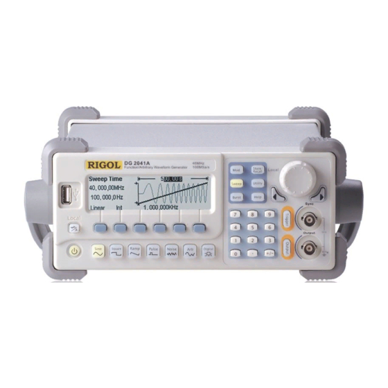
Rigol DG2000 Series User Manual
Function/arbitrary waveform generator
Hide thumbs
Also See for DG2000 Series:
- User manual (146 pages) ,
- Performance verification manual (48 pages) ,
- Quick manual (16 pages)


Need help?
Do you have a question about the DG2000 Series and is the answer not in the manual?
Questions and answers