
Subscribe to Our Youtube Channel
Related Manuals for Triax MCT 049B


Summary of Contents for Triax MCT 049B
- Page 1 User manual TRIAX TV meters MCT 049B / MCT 059B Model Item no. 812963 TRIAX TV meters MCT 049B / MCT 059B 812972 07/2020 Version Date...
- Page 2 This product contains one or more programs protected under international and US copyright laws as un- published works. They are confidential and proprietary to Dolby laboratories. Their reproduction or disclo- sure, in whole or in part, or the production of derivative works there from without the express permission of Dolby Laboratories is prohibited.
- Page 3 Thank you for purchasing this TRIAX product and therefore trusting our company. Our different teams (research department, production, sales department, after-sales service…) are aiming at satisfying your wishes by designing and updating very advanced appliances. To obtain the best performance from this product please read this manual carefully.
- Page 4 It shall subscribe, at its own expenses, any insurance required for the transport. The TRIAX company reserves the right to refuse any product wrongly conditioned and not to take in charge any break consec- utive to the transport.
- Page 5 March 1, 2015: Spare parts are not available to the consumer. TRIAX offers the supply of spare parts during repair by its service. Consumable parts are provided according to the legislation applicable to them (case of batteries).
-
Page 6: Table Of Contents
TABLE OF CONTENTS Important information ......................9 Particular precautions ............................. 9 Security instructions ............................9 Symbols and definitions ..........................9 Presentation ........................11 General ................................. 11 Description of the appliance ......................... 12 Power-up ..........................13 Battery ................................13 Battery charge .............................. 14 External power supply .......................... - Page 7 Check of the targeted transmitter ......................... 44 10 AUTOSET mode ......................... 45 10.1 Terrestrial mode ............................46 10.2 Satellite mode ............................46 10.3 Cable Mode .............................. 46 10.4 «START » menu key ..........................47 11 Measures ..........................48 11.1 Modification of parameters ........................49 11.2 Utilisation de la Liste de mesure .......................
- Page 8 17.1 Out of tolerance values ..........................76 18 Optical measurement MCT 059B ..................77 18.1 Presentation of the optic measurement ....................77 18.2 What you need to know ..........................78 18.2.1 The optical fiber ............................. 78 18.2.2 Connectors ............................79 18.3 Optical power measurement ........................
-
Page 9: Important Information
• In case of failure or for the maintenance of the appliance, only a qualified personal shall be entitled to work on it. In such a case, it is required to use TRIAX spare parts. • Do not open the appliance: risk of electric shock. - Page 10 Symbols on the appliance: Attention: Refer to the manual. Shows a risk of damage for the material connected to the in- strument or to the instrument itself. Ground: Grounded accessible parts. Product for recycling.
-
Page 11: Presentation
2 Presentation General The field strength meters MCT 049B-MCT 059B are appliance designed for the installation and maintenance of any broadcasting and reception installations of analogical and digital terrestrial television channels, satel- lites or cable networks, for RF or optical modulated signals. -
Page 12: Description Of The Appliance
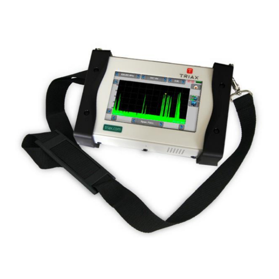
Description of the appliance 7’’ capacitive touchscreen high resolu- Fastening tion for straps RF socket with F/F adapter Optical FC APC input Remote supply light with protective plug Ethernet socket USB A socket ON/OFF switch RF F output of the optical option to link to the RF F input of the appliance via the pro-... -
Page 13: Power-Up
In order not to damage your screen, do not use a stylus or object. Battery Attention: Any intervention on the battery requires the disassembly of the appliance and should be made by a TRIAX technician. Use only batteries provided by TRIAX. Security advice: ➔... -
Page 14: Battery Charge
Battery charge To charge the battery inside the appliance: • Connect the external power supply provided through the jack plug of the appliance (above) • Connect the power supply on the mains • The internal charger starts loading the battery; the green lamp lights up. Charge the device only when the device is off. -
Page 15: Quick Start-Up
4 Quick start-up Installing a TERRESTRIAL antenna You have two methods to install a terrestrial antenna : • using the POINTING function • using the SPECTRUM function 4.1.1 Use of the POINTING function The appliance gets an “Antenna pointing” mode in order to align quickly and easily your terrestrial antenna. To access to the “Antenna pointing”... - Page 16 ➔ The key validates your transmitter by displaying the TV channels of each channel : The 4 frequencies or channels of the transmitter you are trying to point are changeable depending on your loca- tion : You can save a new transmitter to find it among the possible 10 :...
-
Page 17: Use Of The Spectrum Function
4.1.2 Use of the SPECTRUM function Turn your appliance on. Press the Measures key Press the Spectrum function ➔ Access to full SPAN mode ➔ Choose a known CHANNEL : ➔ Adjust slowly the antenna to get the most powerful signal possible... - Page 18 ➔ Press the NIT key , the device find automatically all the parameters of the signal. Once the search ended, the device display the “Network Name” and the “Network ID”. You can now do all the measurements, level, BER/MER and access the TV display :...
-
Page 19: Installing A Satellite Dish
Installing a SATELLITE dish You have two methods to install a satellite dish : • using the POINTING function • using the SPECTRUM function 4.2.1 Use of the POINTING function The appliance gets an “Dish pointing” mode in order to align quickly and easily your satellite dish. To access to the “Check Sat”... - Page 20 Reminder: a satellite antenna must be powered by direct current: remote power supply To access to the Remote power supply page, press Check for tension and current consumed by your dish’s LNB : ➔ To check if the aimed satellite is the right one : press the NIT key The appliance searches the MPEG NIT table on one of the 4 transponders and displays the name of the sat- ellite: Attention:...
- Page 21 The 4 frequencies or transponders of the satellite you are trying to point are editable : Attention: To identify a satellite, you must be locked on all 4 transponders. (Quality > 0) However, some transponders are regularly modified. See the frequency range of the sat- ellite when a transponder does not seem to work.
-
Page 22: Use Of The Spectrum Function
4.2.2 Use of the SPECTRUM function Turn your appliance on. Press the Measures key Press the Spectrum function ➔ Access to full SPAN mode ➔ ➔ Choose a known TRANSPONDER : ➔ Adjust slowly the dish to get the most powerful signal possible... - Page 23 Reminder: a satellite antenna must be powered by direct current: remote power supply To access to the Remote power supply page, press Check for tension and current consumed by your dish’s LNB :...
- Page 24 ➔ Then press the button . The device automatically searches for signal settings. Once the search is complete, the device displays the "Network Name" and the "Network id" You can now do all the measurements, level, BER/MER and access the TV display :...
-
Page 25: Verifying An Installation
Verifying an installation The device allows you to check an existing RF signal distribution installation, whether on terrestrial, satellite, by coaxial cable or optical fiber. An AUTOSET function automatically detects all distributed channels, and scans them one after the other through the MEASUREMENT MAP function. -
Page 26: Man-Machine Interface
5 Man-machine interface Content of the screen The appliance has a capacitive touchscreen. No glove should be used. If you don’t want to damage your screen, do not use any stylus or object. You can recognize the« keys » by their dark grey frame, example the Home key: Home Access to the main menu page... - Page 27 To navigate through a table inside a page or a window, a vertical slide appears with arrows to move up and down the table. To move faster, you can slide a cursor with your fingers. Move up through the table Cursor to navigate up or down To validate the choice of a line of a table, simply press this line: choosing a program/channel, choosing a...
-
Page 28: Lists Of Measurements And Setup Library
Lists of measurements and setup library In order to make easier the recall of data on field, the appliance uses 20 Measurement Lists of each 50 lines and 1000 setups from a Library. A setup corresponds to a terrestrial, cable or satellite emission. A list of measurements corresponds to a particular installation: presence of several satellite dishes, of vari- ous switches…... - Page 29 A list of measurements is made of: • a list name in 10 characters • the lowest frequency of the LNB (OL1) • the highest frequency of the LNB (OL2) • the selection mode low band / high band of the LNB •...
-
Page 30: Measurement Lists
6 Measurement lists The list page In this page, you can select the list where you will work on measurements. Pressing Home then Lists-Library gives you access to the Lists function: Lists are ranked from 0 to 19. To select the one you want, press the following key. Lists are displayed. Press the one you want: In this example, we selected ST ETIENNE. -
Page 31: Modification Of A List
To change the name of the list of ST ETIENNE, you must push on its name, then on the symbol of the key- pad. A virtual keypad shows up. Type the new name (TRIAX in our example). To add a setup to the list, select the line. A window shows up: Attention: If the line contains a setup, it shall be erased. - Page 32 Scroll the list up or down to find the setup you want to add to your list. Press the line you want: The setup is now in the list: You may erase the setup from the list by pressing the check to the left of the setup or to the setups you have to delete.
- Page 33 You can also delete the totality of a list by pressing directly on the basket then by selecting In a satellite setup, you can change the switch, the Uncommitted Port and the DCSS by activating any of these keys (this change will affect only the setup in this list, not in the library):...
-
Page 34: Setup Library
7 Setup library The library page By pressing Home then Lists-Library , you can access the Lists function. From there, you can access the Library by pressing the key Creation or modification of setups in the library To create or change a setup in the library, you have to select a line in the table. A window pops up: Attention: If the line contains a setup, it will be erased. - Page 35 You may erase the setup from the list by pressing the check to the left of the setup or to the setups you have to delete. Then click the basket and select the deletion of the selected setup: From this window, you can create a terrestrial, satellite KU, L or C setup. To proceed, see chapter 5 Man-machine interface ➢...
- Page 36 ➢ Satellite Setup : To enter the type of polarity you want for the setup (high or low, vertical or horizontal) To enter the symbol rate you want for the setup...
-
Page 37: Check Sat
8 Check Sat Press to access the Check Sat mode. Functioning Name and position of the satellite Global quality indi- cation Frequency, polarization, band, level and quality The appliance has 32 possible orbital positions for satellites. It is provided with near of 10 satellites regis- tered. -
Page 38: Updating Satellites
You can update frequencies of the checks sat : manually on your device by importing the configuration posted on the TRIAX website. All you have to do is to copy this file on a USB stick and go to "Configuration" and then "Import"... -
Page 39: Checking The Aligned Satellite
If the appliance is not synchronized on all four transponders, the quality indication is red. If the appliance is synchronized on all four transponders but the reception quality is aver- age, the quality indication is orange. Good reception quality (> 50%) → green smiley Attention: 4 transponders To identify a satellite, it must be synchronized on all... -
Page 40: Double Check Sat
Attention: The displayed name depends on the content of the MPEG NIT table. Some distributors provide no (or poor) such table. The displayed information may be wrong. Double Check Sat This mode allows you to orientate a double LNB by checking 4 transponders on 2 selected satellites. A dual LNB consists of 2 single LNB, plus a built-in DISEQC switch. -
Page 41: Recall
8.5.1 Recall Azimut Position of the satellite dish on the horizontal plane with reference to the north. Measured in degrees. Elevation Tilt angle under which the beam from the satellite reaches your antenna. Measured in degrees using what is specified on the stand of the satellite dish. Polarization Rotation required for the LNB from a vertical line. -
Page 42: Terrestrial Check
9 TERRESTRIAL check To access to the menu terrestrial check from Home page, press Functioning Transmitter name Global quality indicator Frequency, channel, standard, level and quality The device has a list of 10 possible transmitters. The device comes with a few informed transmitters. Each transmitter is associated with 4 channels. -
Page 43: Transiter Update
Transiter update You can update the frequencies/names of transmitters : manually on your device by importing the configuration from the TER file. Csv All you have to do is to copy this file on a USB stick and go to « Configuration » then « Import » Instruction for use 1/ Connect the antenna to the device and turn it on. -
Page 44: Check Of The Targeted Transmitter
If the device is not synchronized across all four channels, the quality indicator is red. If the device is synchronized across four channels and the reception quality is average, it is orange. If the device is synchronized across four channels and the reception quality is good, it is green. -
Page 45: Autoset Mode
10 AUTOSET mode This mode allows an automatic research of setups and to provide information about the current place. You can access it through the key on page Home. Attention: The Autoset channel research is only possible when at least one list is empty with enough place in the library The displayed lines on this page depend on the selected Frequency band. -
Page 46: Terrestrial Mode
Once the mode selected, the keys of the various parameters activate or deactivate each option. A green check shows that the parameter is included in the research. If there is no green check, the param- eter will not be taken into account for the research. Active research parameter Inactive research parameter Attention: The more you select options, the longer is the research. -
Page 47: Start " Menu Key
10.4 «START » menu key No matter which mode is selected, press the “START” key to launch the research. Pressing “Stop” will abort the research. When the research is done or if the user aborted it, the appliance turns automatically to the Measure- ment map function. -
Page 48: Measures
11 Measures Pressing the MEASURE zone gives access to the MEASURES function. In this page, you can either perform measurements : - by inputting signal parameters - on a memorized program in the current list (see chapter « Measurement list ») - use the “... -
Page 49: Modification Of Parameters
11.1 Modification of parameters The various parameters are: • The name of the setup (selection on the active list) • The frequency of the emitter or transponder (and the true frequency of satellite) • The standard and bandwidth for DVB-T/H and DVB-T2 •... -
Page 50: Autolock Function
11.3 Autolock function This function is design to lock on a digital signal (terrestrial, cable or satellite) You just have to enter the frequency or the channel (for terrestrial), then press AutoLock, The instrument will find automatically in few seconds the digital standard, the modulation type and all other parameters of the signal. -
Page 51: Satellite Band
The appliance makes different measurements according to the current standard. The other possible measurements are: • Average measurement • Peak measurement • Power measurement. 11.4.1 Satellite band The following table sums up the measurement types and the frequencies of the audio carrier waves for each standard: Standard porteuse vidéo... -
Page 52: Thresholds
The appliance displays the level of the Video carrier wave and the C/N ratio. 11.4.3 Thresholds Predefined thresholds are used to assess if the measurement is pertinent. Standard Terrestrial analog TV DVB-C/C2 DVB-T/T2 DAB-DAB+ FM, Carrier Satellite analog TV DVB-S, DSS DVB-S2 min threshold max threshold... -
Page 53: Dvb-T
You can shift from terrestrial to satellite mode by: - Changing the setup frequency - Changing of standard - Changing of setup (from a terrestrial to a satellite setup) 11.6 DVB-T REED DECODAGE VITERBI DEMODULATEUR TUNER SOLOMON MPEG BERi BERo Display of the measures of: •... -
Page 54: Dvb-T2 /T2 Lite
11.7 DVB-T2 /T2 Lite DECODAGE DEMODULATEUR LDPC TUNER MPEG BERo BERi Display of the measures of: • BERi: error rate before LDPC • BERo: error rate after LDPC • PER: error rate after BCH (lost packets) • MER: modulation error rate •... -
Page 55: Dvb-C
11.8 DVB-C REED DECODAGE DEMODULATEUR TUNER SOLOMON MPEG BERo Display of the measures of: • BERo: error rate before Reed Solomon • PER: error rate after Reed Solomon (error rate packet) • MER: modulation error rate • LKM: Noise margin (Link Margin) error rate ‘bits’... -
Page 56: Dvb-C2
11.9 DVB-C2 DECODAGE DEMODULATEUR LDPC TUNER MPEG BERo BERi Display of the measures of: • BERi: error rate before LDPC • BERo: error rate after LDPC • PER: error rate after BCH (lost packets) • MER: modulation error rate • LKM: noise margin (Link Margin) Recall:... -
Page 57: Dvb-S / Dss
11.10 DVB-S / DSS REED DECODAGE VITERBI DEMODULATEUR TUNER SOLOMON MPEG BERi BERo Display of the measures of: • BERi : error rate before Viterbi • BERo : error rate after Viterbi • PER : error rate after Reed Solomon (error rate paquet) •... -
Page 58: Dvb-S2 / S2X
11.11 DVB-S2 / S2X DECODAGE DEMODULATEUR LDPC TUNER MPEG BERo BERi Display of the measures of: • BERi : error rate before LDPC • BERo : error rate after LDPC • PER : error rate after BCH (lost packets) • MER : modulation error rate •... -
Page 59: Multistream
11.12 Multistream The 'Multistream' option allows you to view a DVB-S2 signal that uses Multiple Transport Stream technology (several multiplexes are transported on the same transponder simultaneously). Eutelsat 5 West A 5°W Example: broadcasting of the two multiplexes of the TNT on inside the same tran- sponder Frequency: 12648MHz Vertical, DVB-S2 29500, ISI: 1, Gold code: 121212... -
Page 60: Spectrum Analyzer
12 Spectrum analyzer Pressing SPECTRUM gives access to the SPECTRUM ANALYSER function. (graphical representation frequency / amplitude of the present signals in the input of the device) Satellite Terrestrial 2 predefined bandwidths are available: terrestrial and satellite. To swap from satellite to terrestrial, press the key, as shown on the bottom side of the screen. The input attenuator is automatically tuned according to the level of the signals measured. -
Page 61: Image And Sound
13 Image and Sound Pressing the TV zone gives access to the TV function. 13.1 Digital TV The name of the service and its main characteristics are displayed on top left of the screen. • image resolution (e.g. HD 1920x1080i:1920 pixels per line, 1080 lines, interlaced scan) •... -
Page 62: External Analog Video
13.2 External analog video The button allows you to switch to analog external video You can view the analog image PAL, SECAM or NTSC of the analog outputs of set-top boxes, cameras, video doormen ... 13.3 Audio To set the volume, press an adjustment bar shows up: The instrument can decode the following digital sound formats: MPEG-1 L1/L2... -
Page 63: Table Of Services
13.4 Table of services Pressing gives access to the list of services: This function allows selecting the channel you want to display. You only have to press the line you want. -
Page 64: Remote Power Supply / Lnb - Diseqc
14 Remote power supply / LNB – DiSEqC key gives you access to the Remote power supply / LNB-DiSEqC. In Terrestrial, for example, you can power a line amplifier on your installation. In Satellite, you can control all the DiSEqc equipment present on your installation. To start the remote power supply, press the key Remote supply: 14.1 Terrestrial band... -
Page 65: Satellite Band
A green check shows which voltage is selected. 14.2 Satellite band 14.2.1 Power ON Setting the remote power supply to satellite: OFF to turn off the remote power supply under satellite measure ON to turn on the remote power supply under satel- lite measure AUTO to launch au- tomatically the re-... -
Page 66: Lnb Type
14.2.2 LNB type You must choose the type of LNB (parable Low Noise Block head) present on your installation. • L band : no LNB head BIS frequencies (satellite intermediate frequencies) from 200 to 2400MHz no local oscillator frequency (OL) •... -
Page 67: Switches
14.2.3 Switches 2-satellite switch 4-satellite switch * 22 kHz * DiSEqC Committed or Uncommitted * ToneBurst (MiniDiSEqC) *DiSEqC Committed or Uncommitted Uncommitted 16-satellites switch * DiSEqC Committed + Uncommitted... -
Page 68: Motorized Satellite Dish Control
Switch line Uncommitted line Satellite Position Commande DiSEqC Position Commande DiSEqC Pos A Option A + Position A Pos 1 Input 1 Pos B Option A + Position B Pos 1 Input 1 Pos C Option B + Position A Pos 1 Input 1 Pos D... -
Page 69: Dcss
14.2.5 DCSS Description: DCSS Digital Channel Stacking system: signal distribution system using frequency transposition. Used in satellite distribution for multiple or single dwelling, with several set top boxes. To give several receptors access to the whole spectrum and all polarizations, you need one coaxial cable per receptor and a suitable installation (multiple LNB, Quattro and multi-switches). -
Page 70: Satcr (En50494)
2 Modes : SATCR : Satellite Channel Router, standard EN50494 (or SCD, Unicable, …) Distribution of the satellite signal with only one coaxial cable to 2, 4 or 8 different receptors. SCD2 : Single Cable Distribution v2, standard EN50607 (or SCD2, Unicable II, JESS) Distribution of the satellite signal with only one coaxial cable to a maximum of 32 different receptors. -
Page 71: Scd2 (En50607)
14.2.7 SCD2 (EN50607) • SLOT x: active Slot choice • CONFIG: access to each slot configuration Slots list, frequencies, PIN codes, bandwidth • INITIALISATIONS : 32 predefined slots • ALLOCATION : states of the 32 possible slots • DETECT : automatic detection of slots (DISEQC2.0 based) 14.2.8 Influence of the DCSS on the spectrum analyzer... -
Page 72: Constellation
15 Constellation key gives you access to the CONSTELLATION function. These measures are available if one of these standards is running in the LEVEL MEASUREMENT page. • DVB-T/T2 • DVB-C/C2 • DVB-S/S2, DSS The appliance displays the Constellation of the current signal. The information displayed on the right of the Constellation diagram is: •... -
Page 73: Multipath / Guard Interval
16 Multipath / Guard interval Available only for DVBT/T2 or DVB-C2 standards. Pressing allows you to access to Multipath / Guard interval measurement. Signal without echo Signal with echoes and pre- echoes Pressing changes the horizontal scale (distance). Horizontal scale can be set in µs, km or miles by pressing Moving measurement arrow can be done by screen touch, or by automatic search keys The end of the guard interval is displayed with a yellow line. - Page 74 In digital TV DVB-T/T2, these echoes may help or degrade the image according to the time delay between the various signals that reach the antenna. The broadcasting norms DVB-T and DVB-T2 define a modulation parameter called "guard interval" where echoes won't disturb the reception. The transmission of digital data (Symbol) is interrupted during the guard interval.
-
Page 75: Measurement Map
17 Measurement map To access the MEASUREMENT MAP function, press Home then Measurement map: It is an automatic level and error rate measurement of the setups in the measurement list with labeling of the levels beyond tolerance. Measurement result for chan- nel 38 under DVB-T/H BERi, BERo and PER are generic terms (frequently used) -
Page 76: Out Of Tolerance Values
Important: A bargraph above the Measurement map allows you to track the evolution of the scan. The background color of this bargraph shows you that a complete scan has been made (for a save, for example): red: the measurement map has not been totally scanned yet green: the measurement map has been totally scanned In case of mixed measurement map (terrestrial+satellite), the satellite remote power supply has priority (the terrestrial remote power supply is ignored). -
Page 77: Optical Measurement Mct 059B
18 Optical measurement MCT 059B The MCT 059B model has an optical fiber input dedicated to installations that use optical fiber to distribute the RF signal (RF over Fiber). 18.1 Presentation of the optic measurement The Optic function allows measurements in various kind of installations : in satellite reception with fiber wiring (LNB optical fiber output) after a satellite / terrestrial coupler The function :... -
Page 78: What You Need To Know
18.2 What you need to know A few notions are required before considering the use of optical fibers. 18.2.1 The optical fiber Optical fibers are sometimes used for satellite reception. This technology enables makes it possible to transmit a signal further with less loss and with a larger bandwidth. The optical fiber is a waveguide, generally made of glass, that enables the transmission of the optical sig- nal. -
Page 79: Connectors
18.2.2 Connectors Like for RF, connectors are very important and their selection has consequences on the quality of the re- ceived signal. With optical fibers, there are several kinds of connectors according to the type of fiber (single-mode or mul- timode) and to the selected connection. -
Page 80: Optical Power Measurement
18.3 Optical power measurement To access the Measurement of Optical Power, press the key “Optical power measurement”. Warning: The appliance can measure only one wavelength at a time. If there are several wave- lengths, measurements will be wrong. Plug the optical fiber at the output of your equipment on to the optical FC APC socket of the appliance. Measurement of the losses at insertion: Make a first measurement at the LNB of your installation: press the reference of the desired wavelength. -
Page 81: The Satellite Reception Via Optical Fiber
18.4 The satellite reception via optical fiber With optical fibers, the satellite emission is the same as in standard reception mode, but at the output of the head, instead of 4 bands (HH HL VH VL), there are only 2 bands (vertical and horizontal) in optical signal mode (the optical head is powered by an independent external power supply). -
Page 82: Fiber Reception After Coupler
18.5 Fiber reception after coupler The optical option makes it possible to make measurements after terrestrial coupler / sat at the output of the fiber. Warning: The appliance can measure only one wavelength at a time. If there are several wavelengths, measurements will be wrong. - Page 83 Warning : - Optical Power measurement between -50 / +10 dBm - Optical conversion -> RF between -12 / -3 dBm Use an external optical attenuator if necessary.
-
Page 84: Configuration
19 Configuration For configuration, go to the Home page, then Configuration 19.1 Language You can select your language by pressing the « flag » (below). Press the flag corresponding to your language: 19.2 Measurement unit This key allows you to select the measurement unit of the appliance: •... -
Page 85: Frequency Map
19.3 Frequency map This key allows you to select the terrestrial frequency map of the appliance: 19.4 Memories To save a picture or any other feature, see chapter Save The number of saved file and their memory size are displayed. When pressing this key, a pull-down menu lists the previously saved files. -
Page 86: View
By pressing a line of the table, you open a window: 19.4.1 View This key allows the display of the content of the file: info : device, file name... -
Page 87: Save
19.4.2 Save Save (BMP -> USB) allows you to export the file to the USB stick under BMP format (non-compressed graph); it is useful to transfer graphs to a report in a PC computer. Here is the BMP file of the previously displayed DVB-T/H channel, edited on PC to have the spectrum full screen. -
Page 88: Update
- Save all (BMP -> USB) records all files from the appliance under BMP format into separated registers: • LEVEL for the level measurements • MAP for the measurement maps • SPECTRUM for the spectrum measurements • BER-MER for the error rate measurements •... -
Page 89: Configuration Import/Export
You can make a backup on a USB stick of your setups/lists of your appliance by pushing « « Configuration Export ». And you can import from a USB stick this configuration with the touch “Configuration import”. You can also update checksat/antenna pointing configuration available on TRIAX’s website. -
Page 90: Software Update
USB stick. To achieve the update: - Download the update ZIP file on our website (www.triax.com) - Insert a USB stick on your PC - Unzip the file onto the root of the memory stick... -
Page 91: Save
21 Save Pressing opens a window (here, on the Measurement page): In this window, you can save the current measurement parameters from the active list, make a screen shot to a USB stick under BMP format or make a save into internal memory. You can rename the save file. -
Page 92: Connection Of The Appliance To A Pc
22 Connection of the appliance to a PC The appliance has an ETHERNET interface that makes it possible to connect directly to a PC. For this type of connection, no driver is necessary. Connect your appliance to your PC by using a crossed ETHERNET cable (available in option). Configuration of the connection: Ethernet connection of your appliance to the PC. - Page 93 Attention: If the PC has already been connected to Ethernet (network, modem…), it is necessary to reboot the PC before connecting your appliance. For the Ethernet connection of your appliance to a computer network, see the following scheme: 1) Contact your network adminis- 2) Type the IP address and trator to get a free IP address the subnet mask in the ap-...
-
Page 94: Displayed Messages
23 Displayed messages The appliance may display messages while working. 23.1 Alert messages Low battery: the appliance is about to shut off in a few minutes. Confirmation request for an important action. Remote power supply issue: voltage already present or maximum current exceeded. -
Page 95: Error Messages
A message may show up at the bottom of the screen immediately after updating the software. Do not take care of as far as it does not show up at a second start-up. Else, or for any other problem, contact the TRIAX technical support. -
Page 96: Maintenance
At each use, check the state and cleanliness of the patchcord patchcord This "advice" does not engage the responsibility of TRIAX. It guarantees the best possible use of the characteristics and the preservation of the product. Routine maintenance: The basic maintenance is simply cleaning the outside of the appliance. Any other operation requires a trained personal. - Page 97 100% good functioning pixels in the display zone. They specify a number of possible de- fective pixels at the surface of the screen. The TRIAX quality service has preconditioned the mounting of the screen on your instrument to the respect of the acceptance conditions of the manufacturers.
-
Page 98: Technical Specifications
25 Technical specifications 25.1 Selection guide MCT 049B MCT 059B 7817B Frequencies 5-2400MHz 5-2400MHz 5-1005MHz DVB-T/T2/T2 Lite DVB-C/C2 DVB-S/S2, DSS, Multistream DVB-S2X MPEG2/4, SD/HD A/V analog video input ... -
Page 99: Technical Specifications
25.2 Technical specifications Technical specifications Terrestrial band Satellite band Frequencies Range 5-1005 MHz 200-2400 MHz Resolution measurement 50 kHz, display 1 kHz measurement 1MHz, display 1MHz Level measurements Dynamic range 20-120 dBµV 20-120 dBµV Units dBµV, dBmV, dBm Accuracy 2dB +/- 0.05dB/°C Resolution 0,1dB Measurement Filters... -
Page 100: Digital Measurements
25.3 Digital measurements DVB-T CBER (before Viterbi BERi) VBER (after Viterbi BERo) Bit Error Rate (BER) UNC (lost packets PER) Noise margin Modulation Error Rate(MER) 15 - 35dB Sensitivity < 35dBµV Bandwidth 6MHz, 7 MHz, 8 MHz FFT type 2k, 8k Constellation QPSK, 16QAM, 64QAM Viterbi rate... - Page 101 DVB-C J83A BER (before Reed Solomon BERo) Bit Error Rate (BER) UNC (lost packets PER) Noise margin Modulation Error Rate(MER) 20 - 40dB Sensitivity < 55dBµV Symbol Rate 1 to 7.224 Ms/s Constellation 16 / 32 / 64 / 128 / 256 QAM Spectrum inversion auto Standards...
- Page 102 DVB-S, DSS CBER (before Viterbi BERi) VBER (after Viterbi BERo) Bit Error Rate (BER) UNC (lost packets PER) Link margin Modulation Error Rate(MER) 0 - 20dB Sensitivity < 47dBµV Symbole rate 1 to 50Ms/s Constellation QPSK Viterbi rate 1/2, 2/3, 3/4, 5/6, 7/8 Spectrum inversion Auto Standards...
- Page 103 Gold code 0 to 999999...
-
Page 104: Optical Measurements (Mct 059B)
25.4 Optical measurements (MCT 059B) Optical fiber input Wavelengths 1310nm, 1490nm, 1550nm Connector FC/APC Optical power measurement Measurement dynamic -50.0dBm to +10dBm Accuracy +/- 0.5dB Optical to RF converter Conversion dynamics -12dBm to -3dBm Input optical bandwidth 50MHz to 5450MHz Converted RF terrestrial bandwidth 50 to 900MHz Converted RF satellite bandwidth... -
Page 105: Divers
25.5 Divers Remote supply Terrestrial Satellite 5V/13V/18 V/24V 13/18 V Voltage 500 mA max (300mA for 24V) 500 mA max DiSEqC 2.1 control of dish motor DiSEqC switches committed & uncommitted bi-directionnal 22 kHz, ToneBurst Mini DiSEqC (22kHz) SCD /SATCR EN 50494 8 slots max Single cable satellite distribution... -
Page 106: General Specifications
Luxury backpack • Sun protector + Rain protector + coat hook • Rain protector Contact our sales department TRIAX. Contact TRIAX's sales department. 25.8 dBµV, dBmV et dBm conversion • dBμV is a logarithmic ratio between a measured voltage Ud and a reference voltage Ur. -
Page 107: Typical Values For Measurements
• dBmV is a logarithmic ratio between a measured voltage Ud and a reference voltage Ur. The reference voltage is Ur = 1 mV N = 20 log (Ud/Ur) • dBm is a logarithmic ratio between a measured power Pd and a reference power Pr. The reference power is Pr = 1 mW into 75 ohms. -
Page 108: Terminology
26 Terminology K : The number of carrier waves of the DTT channel The 8K mode (6817 carrier waves in the channel, including 6048 carrying useful data) The 2K mode (1705 carrier waves in the channel, including 1512 carrying useful data) For the same purpose, the 8K mode allows the selection of a larger guard interval than the 2K mode, thus a better resistance to echoes : Method used to highlight the characteristics of the signal. - Page 109 mode). : Control mean for the quality of the signal by a group of points making spots on the ONSTELLATION screen of the field meter. The more circular and distinct the spots of the constellation, the better the quality of the signal.
- Page 110 REQUENCY: Parameter that characterizes the radio-electrical wave. It is measured in “Hertz“. We usually use some multiples of this unit: kilohertz (kHz), megahertz (MHz), gigahertz (GHz). ex.: At Saint Etienne (Guizay), the TF1 frequency is 583.25 MHz P/LP: high/low priority → possibility to transmit 2 multiplexes under the same channel in digit format ( ex.: in COFDM, we have a very robust high priority flow in QPSK;...
- Page 111 The MPEG 2 option on the TRIAX field meters allows you to view and control TV programs (coded under MPEG) directly on the meters.
- Page 112 LP : (Physical Layer Pipe) from 1 to 256 channels are available in DVB-T2 to transport inde- pendent multiplexes. OLARIZATION: Polarization of a signal from the satellite. It can be either: linearly polarized, horizontally or vertically: Circularly polarized to the right or the left In ground reception, the polarization is generally horizontal (the stalks of antennas are horizon- tal).
- Page 113 : Decryption systems used in Europe by many operators (TPS, Canal IACCESS EDIAGUARD Satellite…). With the Viaccess and Mediaguard options in a TRIAX field meter and your subscription card, you will be able to view encrypted programs on the meter. : An algorithm used to correct errors in digital transmissions...
- Page 114 Peut être sujet à modification sans préavis Copyright © 2020 TRIAX. All rights reserved. The TRIAX Logo and TRIAX Multimedia are registered trademark(s) of the TRIAX Company or its affiliates. TRIAX A/S | Bjørnkærvej 3 | 8783 Hornsyld | Denmark...
Need help?
Do you have a question about the MCT 049B and is the answer not in the manual?
Questions and answers