Mark-10 Series 3 User Manual
Digital force gauges
Hide thumbs
Also See for Series 3:
- Quick start manual (3 pages) ,
- User manual (21 pages) ,
- User manual (20 pages)
Table of Contents
Advertisement
Advertisement
Table of Contents

Related Manuals for Mark-10 Series 3


Summary of Contents for Mark-10 Series 3
- Page 1 Series DIGITAL FORCE GAUGES User’s Guide Office: Jl. Radin Inten II No. 62 Duren Sawit, Jakarta 13440 - Indonesia Mobile: +62 816 1740 8925 Workshop: Jl. Pahlawan Revolusi No. 22B, Jakarta 13430 - Indonesia Fax: 021-8690 6777 Phone: 021-8690 6777 (Hunting)
-
Page 2: Table Of Contents
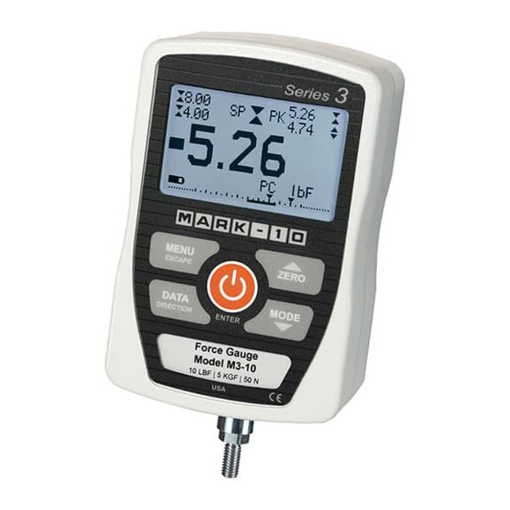
Thank you for purchasing a Mark-10 Series 3 digital force gauge, designed for tension and compression force testing applications from 0.12 lb to 500 lb (0.5 N to 2,500 N) full scale. The Series 3 is an essential component of a force testing system, typically also comprising a test stand, grips, and data collection software. -
Page 3: Overview
User’s Guide Series 3 Digital Force Gauges 1 OVERVIEW 1.1 List of included items Part No. M3-012 – M3-50 – M3-200 – Qty. M3-20 M3-100 M3-500 Description 12-1049 12-1049 12-1049 Carrying Case AC1030 / AC1030 / AC1030 / AC adapter body with US, EU, or UK prong... -
Page 4: Power
User’s Guide Series 3 Digital Force Gauges accumulate in the sample during testing. Extra bodily protection should be worn if a destructive failure of a test sample is possible. 6. In certain applications, such as the testing of brittle samples that can shatter, or other applications that could lead to a hazardous situation, it is strongly recommended that a machine guarding system be employed to protect the operator and others in the vicinity from shards or debris. -
Page 5: Mechanical Setup
The round steel insert with a hole in the back of the housing is provided to withstand the load during a test. A mating dowel pin should be used (see illustration below). Mounting plates on Mark-10 test stands include a dowel pin and clearance holes for the four threaded holes located near the corners of the housing. -
Page 6: Home Screen And Controls
User’s Guide Series 3 Digital Force Gauges operator and others in the vicinity. If using a grip or fixture from a supplier other than Mark-10, ensure that it is constructed of suitably rugged materials and components. Do not use jam nuts or tools to tighten grips or attachments onto the shaft. Finger-tighten only. - Page 7 User’s Guide Series 3 Digital Force Gauges Mode The current measurement mode. Abbreviations are as follows: RT – Real Time PC – Peak Compression PT – Peak Tension See Operating Modes section for details about each of these modes Battery / AC...
-
Page 8: Operating Modes
5.3 Peak Tension (PT) Same as Peak Compression, but for tension readings. 6 CHANGING THE UNITS Series 3 gauges display one of three measurement units. To change the unit, select Units from the menu. The display will appear as follows: UNITS The gauge will always power on with the unit selected. -
Page 9: Set Point Indicators
User’s Guide Series 3 Digital Force Gauges DIGITAL FILTERS (1 = Fastest) Current Reading Displayed Reading 1024 Two filters are available: Current Reading – Applies to the peak capture rate of the instrument. Displayed Reading – Applies to the primary reading on the display. -
Page 10: Communications
Note: Set point indicators reference the displayed reading, not necessarily the current live load. 9 COMMUNICATIONS Communication with Series 3 force gauges is achieved through the micro USB port located along the left side of the housing, as shown in the illustration in the Power section. Communication is possible only when the gauge is in the main operating screen (i.e. - Page 11 5. After Windows as restarted, plug in the device. The following will occur: Windows 7 Operating Systems – When the Mark-10 USB device has been plugged into a USB port, the driver will automatically be found. When the driver installation is complete, a message will appear as follows: “The MARK-10 USB DEVICE driver is now installed and ready to use”.
- Page 12 8. The next, and final, screen appears as follows: Click “Finish”. The Mark-10 USB device is now installed and ready to use. The COM port number assigned by Windows may be identified in Device Manager, or in the communication application being used, such as MESURgauge or HyperTerminal.
-
Page 13: Calibration
User’s Guide Series 3 Digital Force Gauges Configure the baud rate and data format as required for the application. Default values are as follows: Baud Rate: 9,600 Data Format: Numeric + units Other communication settings are permanently set to the following:... - Page 14 User’s Guide Series 3 Digital Force Gauges 3. To escape the Calibration menu at any time, press ESCAPE. The display will appear as follows: CALIBRATION NOT COMPLETE CANCEL EXIT W/O SAVING Selecting “CANCEL” will revert back to the Calibration setup. Selecting “EXIT W/O SAVING” will return to the menu without saving changes.
- Page 15 User’s Guide Series 3 Digital Force Gauges 7. The display will appear as follows: CALIBRATION COMPRESSION Optionally exercise load cell a few times. THEN PRESS ENTER Optionally exercise the load cell shaft several times (at full scale, if possible), then press ENTER.
- Page 16 User’s Guide Series 3 Digital Force Gauges CALIBRATION COMPRESSION COMPLETE REVERSE DIRECTION FOR TENSION Attach necessary weight fixtures. THEN PRESS ENTER Press ENTER. 12. The display will appear as follows: CALIBRATION To invert the display, press the DIRECTION key. THEN PRESS ENTER Reverse the orientation of the load cell shaft by rotating the gauge 180 degrees.
-
Page 17: Other Settings
User’s Guide Series 3 Digital Force Gauges LOAD NOT STABLE PLEASE TRY AGAIN Ensure that the load is not swinging, oscillating, or vibrating in any manner. Then try again. CALIBRATION COMPRESSION LOAD TOO LOW PLEASE TRY AGAIN The calibration weight does not match the set value. - Page 18 User’s Guide Series 3 Digital Force Gauges BACKLIGHT Auto Set Minutes Select Off for the backlight to be off upon powering on the gauge. Select On for the backlight to be on upon powering on the gauge. Select Auto for the backlight to be on upon powering gauge, but will shut off after a period of inactivity (as defined in the Automatic Shutoff sub-section).
- Page 19 User’s Guide Series 3 Digital Force Gauges INITIAL MODE Real Time Peak Compression Peak Tension The default value is Real Time. 11.6 Information / Welcome Screen The following screen is displayed at power up and can be accessed at any time by selecting Information...
-
Page 20: Specifications
User’s Guide Series 3 Digital Force Gauges 12 SPECIFICATIONS 12.1 General Accuracy: ±0.3% of full scale ±1 digit Sampling rate: 2,000 Hz Power: AC or rechargeable battery. Low battery indicator appears when battery level is low, and gauge powers off automatically when power reaches critical stage. - Page 21 User’s Guide Series 3 Digital Force Gauges 12.3 Capacity, Resolution & Load Cell Deflection Load Cell Capacity Resolution Model Deflection in [mm] 0.005 [0.13] 0.12 0.0001 0.05 0.0005 M3-012 0.010 [0.25] 0.25 0.0002 0.001 M3-025 0.0005 0.002 M3-05 0.010 [0.25] 0.002...
- Page 22 User’s Guide Series 3 Digital Force Gauges NOTES: Office: Jl. Radin Inten II No. 62 Duren Sawit, Jakarta 13440 - Indonesia Mobile: +62 816 1740 8925 Workshop: Jl. Pahlawan Revolusi No. 22B, Jakarta 13430 - Indonesia Fax: 021-8690 6777 Phone: 021-8690 6777 (Hunting)
Need help?
Do you have a question about the Series 3 and is the answer not in the manual?
Questions and answers