Mark-10 4 Series User Manual
Digital force gauges
Hide thumbs
Also See for 4 Series:
- User manual (26 pages) ,
- Quick start manual (3 pages) ,
- Quick start manual (2 pages)

Related Manuals for Mark-10 4 Series


Summary of Contents for Mark-10 4 Series
- Page 1 Series DIGITAL FORCE GAUGES User’s Guide 1.800.561.8187 information@itm.com www. .com...
-
Page 2: Table Of Contents
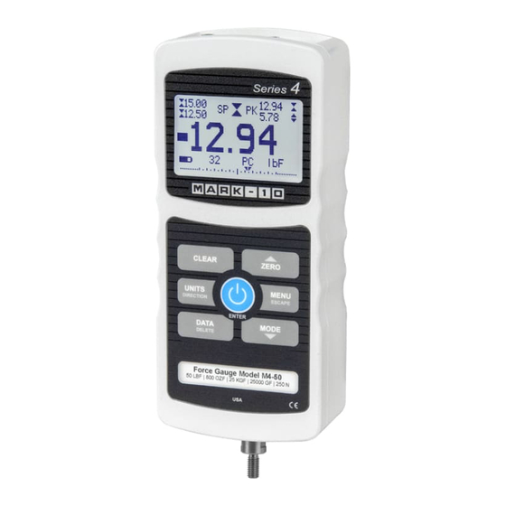
User’s Guide Thank you… Thank you for purchasing a Mark-10 Series 4 digital force gauge, designed for tension and compression force testing applications from 0.12 lb to 500 lb (0.5 N to 2,500 N) full scale. The Series 4 is an essential component of a force testing system, typically also comprising a test stand, grips, and data collection software. -
Page 3: Overview
Series 4 Digital Force Gauges User’s Guide 1 OVERVIEW 1.1 List of included items Part No. M4-012 – M4-50 – M4-200 – Qty. M4-20 M4-100 M4-500 Description 12-1049 12-1049 12-1049 Carrying Case AC1030 / AC1030 / AC1030 / AC adapter body with US, EU, or UK prong AC1031 / AC1031 / AC1031 /... -
Page 4: Power
Series 4 Digital Force Gauges User’s Guide 2 POWER The gauge is powered either by an 8.4V NiMH rechargeable battery or by an AC adapter. Since the batteries are subject to self discharge, it may be necessary to recharge the unit after a prolonged period of storage. -
Page 5: Setup
These holes are designed to accommodate screws in order to hold the gauge in place (Mark-10 test stands include a set of thumb screws for gauge mounting). The screws must not be used for load bearing purposes. Failure to use a dowel pin properly can result in a hazardous situation. - Page 6 If using a grip or fixture from a supplier other than Mark-10, ensure that it is constructed of suitably rugged materials and components. Do not use jam nuts or tools to tighten grips or attachments onto the shaft. Finger-tighten only.
-
Page 7: Home Screen And Controls
Series 4 Digital Force Gauges User’s Guide 4 HOME SCREEN AND CONTROLS 4.1 Home Screen Name Description Tension / - indicates a compression (push) direction compression indicator - indicates a tension (pull) direction These indicators are used throughout the display and menu. Peaks The maximum compression and tension readings. - Page 8 Series 4 Digital Force Gauges User’s Guide RT – Real Time PC – Peak Compression PT – Peak Tension See Operating Modes section for details about each of these modes Number of stored The number of stored data points in memory, up to 50. Displayed only if data points Memory Storage is enabled for the DATA key.
-
Page 9: Operating Modes
Series 4 Digital Force Gauges User’s Guide 4.3 Menu navigation basics Most of the gauge’s various functions and parameters are configured through the main menu. To access the menu press MENU. Use the UP and DOWN keys to scroll through the items. The current selection is denoted with clear text over a dark background. -
Page 10: Digital Filters
Series 4 Digital Force Gauges User’s Guide 6 DIGITAL FILTERS Digital filters are provided to help smooth out the readings in situations where there is mechanical interference in the work area or test sample. These filters utilize the moving average technique in which consecutive readings are pushed through a buffer and the displayed reading is the average of the buffer contents. -
Page 11: Set Points
Series 4 Digital Force Gauges User’s Guide 7 SET POINTS 7.1 General Information Set points are useful for tolerance checking (pass/fail), triggering an external device such as a motorized test stand, or alarm indication in process control applications. Two limits, high and low, are specified and stored in the non-volatile memory of the instrument and the primary reading is compared to these limits. -
Page 12: Data Memory And Statistics
7.4 Using Set Points to Control a Mark-10 Test Stand When using set points to stop/cycle Mark-10 motorized test stands, the upper and lower set points must be set to opposite measuring directions. Both set points must be set, even if the intended application is to stop/cycle at only one of the set points. - Page 13 Series 4 Digital Force Gauges User’s Guide 8.1 View Data All the saved data points may be viewed. The record number is displayed, along with the corresponding value and currently set unit of measurement. Any readings may be deleted individually. To do so, scroll to the desired reading and press DELETE.
- Page 14 Series 4 Digital Force Gauges User’s Guide 8.6 Clear All Data Press ENTER to clear all data from the memory. A prompt will be shown, “CLEAR ALL DATA?”. Select Yes to clear all the data, or No to return to the sub-menu. Shortcut for clearing all data: In the main menu, highlight Memory and press DELETE.
-
Page 15: Communications And Outputs
Series 4 Digital Force Gauges User’s Guide 9 COMMUNICATIONS AND OUTPUTS Communication with a Series 4 gauge is achieved through the micro USB or 15-pin serial ports, as shown in the illustration in the Power section. Communication is possible only when the gauge is in the main operating screen (i.e. - Page 16 Series 4 Digital Force Gauges User’s Guide 9.1.3 Data Communication Individual data points may be transmitted by pressing DATA. Series 4 gauges may also be controlled by an external device through the RS-232 or USB channels. The following is a list of supported commands and their explanations.
- Page 17 Series 4 Digital Force Gauges User’s Guide 9.2 Mitutoyo BCD settings This output is useful for connection to data collectors, printers, multiplexers, or any other device capable of accepting Mitutoyo BCD data. Individual data points may be transmitted by pressing DATA or by requesting it from the Mitutoyo communication device (if available).
- Page 18 Series 4 Digital Force Gauges User’s Guide 9.5 I/O Connector Pin Diagram (DB-15HD female) Pin No. Description Input / Output Signal Ground Tension Overload * Output * RS-232 Receive Input RS-232 Transmit Output +12V DC Input / Output Analog Output Output Compression Overload * Output *...
-
Page 19: Calibration
Series 4 Digital Force Gauges User’s Guide 10 CALIBRATION 10.1 Initial Physical Setup The gauge should be mounted vertically to a test stand or fixture rugged enough to withstand a load equal to the full capacity of the instrument. Certified deadweights or master load cells should be used, along with appropriate mounting brackets and fixtures. - Page 20 Series 4 Digital Force Gauges User’s Guide After the number of calibration points has been entered, press ENTER. The display appears as follows: CALIBRATION OFFSET Place force gauge horizontally, then press ZERO Place the force gauge horizontally on a level surface free from vibration, then press ZERO.
- Page 21 Series 4 Digital Force Gauges User’s Guide The display appears as follows: CALIBRATION COMPRESSION Optionally exercise sensor, then press ENTER Optionally exercise the load cell shaft several times (at full scale, if possible), then press ENTER. The display appears as follows: CALIBRATION COMPRESSION Gain adjust...
- Page 22 Series 4 Digital Force Gauges User’s Guide 11. After all the compression calibration points have been completed, the display appears as follows: CALIBRATION COMPRESSION COMPLETE Reverse direction for Tension Attach necessary weight fixtures, then press ENTER Press ENTER. The display appears as follows: CALIBRATION To invert the display, press the...
- Page 23 Series 4 Digital Force Gauges User’s Guide Any errors are reported by the following screens: CALIBRATION Units must be gF Please try again Press ENTER Displayed at the start of calibration if a disallowed unit is selected. CALIBRATION Load not stable Please try again Ensure that the load is not swinging, oscillating, or vibrating in any manner.
-
Page 24: Other Settings
Series 4 Digital Force Gauges User’s Guide 11 OTHER SETTINGS 11.1 Automatic Shutoff The gauge may be configured to automatically power off following a period of inactivity while on battery power. Inactivity is defined as the absence of any key presses or load changes of 100 counts or less. To access these settings, select Automatic Shutoff from the menu. - Page 25 Series 4 Digital Force Gauges User’s Guide 11.3 LCD Contrast The contrast of the display may be adjusted. Select LCD Contrast from the menu. The screen appears as follows: LCD CONTRAST Set Contrast Press ENTER to modify the contrast. Select a value from 0 to 25, 25 producing the most contrast. 11.4 Tones Audible tones can be enabled for all key presses and alerts, such as overload, set point value reached, etc.
- Page 26 The following screen is displayed at power-up and can be accessed at any time by selecting Information from the menu: Digital Force Gauge Series 4 Model No: M4-50 Serial No: 1234567 Version: 1.0 (c) Mark-10 Corp. 1.800.561.8187 information@itm.com www. .com...
-
Page 27: Specifications
Series 4 Digital Force Gauges User’s Guide 12 SPECIFICATIONS 12.1 General Accuracy: ±0.2% of full scale Sampling rate: 3,000 Hz Power: AC or rechargeable battery. Low battery indicator appears when battery level is low, and gauge powers off automatically when power reaches critical stage. Backlight on: up to 7 hours of continuous use Battery life: Backlight off: up to 24 hours of continuous use... - Page 28 Series 4 Digital Force Gauges User’s Guide 12.2 Factory Settings Parameter Setting Set points Upper Disabled (defaults to 80% of full scale, compression, when enabled) Lower Disabled (defaults to 40% of full scale, compression, when enabled) Filters Current Displayed DATA Key Functions RS-232/USB Output Enabled Mitutoyo Output...
- Page 29 Series 4 Digital Force Gauges User’s Guide 12.5 Dimensions IN [MM] Thread Flat M4-012 – M4-100 #10-32M UNF 5/16 [7.94] M4-200 – M4-500 5/16-18M UNC 5/16 [7.94] 1.800.561.8187 information@itm.com www. .com...
Need help?
Do you have a question about the 4 Series and is the answer not in the manual?
Questions and answers