Mark-10 Series 4 User Manual
Digital force gauges
Hide thumbs
Also See for Series 4:
- User manual (29 pages) ,
- Quick start manual (3 pages) ,
- Quick start manual (2 pages)
Table of Contents
Advertisement
Quick Links
Advertisement
Table of Contents

Related Manuals for Mark-10 Series 4


Summary of Contents for Mark-10 Series 4
- Page 1 Series DIGITAL FORCE GAUGES User’s Guide Office: Jl. Radin Inten II No. 62 Duren Sawit, Jakarta 13440 - Indonesia Mobile: +62 816 1740 8925 Workshop: Jl. Pahlawan Revolusi No. 22B, Jakarta 13430 - Indonesia Fax: 021-8690 6771 Phone: 021-8690 6777 (Hunting)
-
Page 2: Table Of Contents
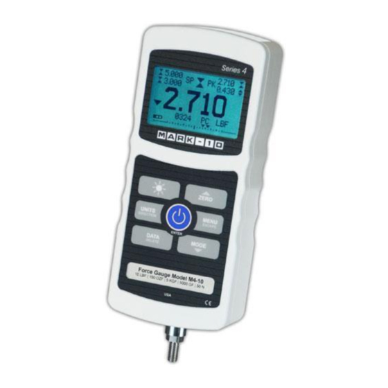
0.12 lb to 500 lb (0.5 N to 2,500 N) full scale. The Series 4 is an essential component of a force testing system, typically also comprising a test stand, grips, and data collection software. -
Page 3: Overview
Series 4 Digital Force Gauges User’s Guide 1 OVERVIEW 1.1 List of included items Part No. M4-012 – M4-50 – M4-200 – Qty. M4-20 M4-100 M4-500 Description 12-1049 12-1049 12-1049 Carrying Case AC1030 / AC1030 / AC1030 / AC adapter body with US, EU, or UK prong... -
Page 4: Power
Series 4 Digital Force Gauges User’s Guide accumulate in the sample during testing. Extra bodily protection should be worn if a destructive failure of a test sample is possible. 6. In certain applications, such as the testing of brittle samples that can shatter, or other applications that could lead to a hazardous situation, it is strongly recommended that a machine guarding system be employed to protect the operator and others in the vicinity from shards or debris. -
Page 5: Mechanical Setup
The round steel insert with a hole in the back of the housing is provided to withstand the load during a test. A mating dowel pin should be used (see illustration below). Mounting plates on Mark-10 test stands include a dowel pin and clearance holes for the four threaded holes located near the corners of the housing. -
Page 6: Home Screen And Controls
Series 4 Digital Force Gauges User’s Guide operator and others in the vicinity. If using a grip or fixture from a supplier other than Mark-10, ensure that it is constructed of suitably rugged materials and components. Do not use jam nuts or tools to tighten grips or attachments onto the shaft. Finger-tighten only. Anti- rotation mounting adapters are available. - Page 7 Series 4 Digital Force Gauges User’s Guide kN – Kilonewton mN – Millinewton Note: not all gauge capacities measure in all the above units. Refer to the capacity / resolution table in the Specifications section for details. Mode The current measurement mode. Abbreviations are as follows: RT –...
-
Page 8: Operating Modes
“OVER” to indicate an overload. A continuous audible tone will be sounded until the MENU key has been pressed or the load has been reduced to a safe level. Three operating modes are possible with Series 4 gauges. To cycle between the modes, press MODE while in the home screen. -
Page 9: Set Points
Series 4 Digital Force Gauges User’s Guide DIGITAL FILTERS (1 = Fastest) Current Reading Displayed Reading Two filters are available: Current Reading – Applies to the peak capture rate of the instrument. Displayed Reading – Applies to the primary reading on the display. -
Page 10: Data Memory And Statistics
8 DATA MEMORY AND STATISTICS Series 4 gauges have storage capacity of 50 data points. Readings may be stored, viewed, and output to an external device. Individual, or all, data points may be deleted. Statistics are calculated for the data presently in memory. -
Page 11: Communications
Note: Data is not retained while the gauge is powered off. 9 COMMUNICATIONS Communication with Series 4 force gauges is achieved through the micro USB or 15-pin serial ports located at the bottom of the instrument, as shown in the illustration in the Power section. Communication is possible only when the gauge is in the main operating screen (i.e. - Page 12 5. After Windows as restarted, plug in the device. The following will occur: Windows 7 Operating Systems – When the Mark-10 USB device has been plugged into a USB port, the driver will automatically be found. When the driver installation is complete, a message will appear as follows: “The MARK-10 USB DEVICE driver is now installed and ready to use”.
- Page 13 Series 4 Digital Force Gauges User’s Guide Select “No, not this time”, then click “Next”. 6. The next screen appears as follows: Select “Install the software automatically (Recommended)”, then click “Next”. 7. The next screen appears as follows: Click “Continue Anyway”.
- Page 14 8. The next, and final, screen appears as follows: Click “Finish”. The Mark-10 USB device is now installed and ready to use. The COM port number assigned by Windows may be identified in Device Manager, or in the communication application being used, such as MESURgauge or HyperTerminal.
- Page 15 Series 4 Digital Force Gauges User’s Guide Any detected errors are reported back by means of the following error codes: *10 Illegal command *11 Not applicable *12 Invalid specifier *22 Value too large 9.3 Mitutoyo BCD settings This output is useful for connection to data collectors, printers, multiplexers, or any other device capable of accepting Mitutoyo BCD data.
-
Page 16: Calibration
Series 4 Digital Force Gauges User’s Guide 9.6 I/O Connector Pin Diagram (female) Pin No. Description Input / Output Signal Ground Tension Overload Output RS-232 Receive Input RS-232 Transmit Output +12V DC Output Analog Output Output Compression Overload Output Mitutoyo Clock... - Page 17 Series 4 Digital Force Gauges User’s Guide 2. Press DIRECTION to invert the display, if desired. ENTER to continue. The display will appear as follows: CALIBRATION ENTER # CAL POINTS (1 TO 10) COMPRESSION: TENSION : The gauge can be calibrated at up to 10 points in each direction. Enter the number of calibration points for each direction (compression and tension).
- Page 18 Series 4 Digital Force Gauges User’s Guide CALIBRATION CALIBRATION OFFSET OFFSET Sen.Offset Adj.Passed Sen.Offset Adj.Failed Ana.Offset Adj.Passed Ana.Offset Adj.Failed If failed: 6. The following screen appears after the offsets have been calculated: CALIBRATION COMPRESSION Attach necessary weight fixtures. THEN PRESS ENTER Attach weight fixtures (brackets, hooks, etc), as required.
- Page 19 Series 4 Digital Force Gauges User’s Guide 10. The display will appear as follows: CALIBRATION COMPRESSION APPLY LOAD 1 OF 5 ENTER LOAD: 2.000 LBF THEN PRESS ENTER Use the UP and DOWN keys to adjust the load value as required. The load values default to even increments, as indicated by the previously entered number of data points (even increments are recommended for best results).
- Page 20 Series 4 Digital Force Gauges User’s Guide 13. At the completion of the tension calibration, the display will appear as follows: CALIBRATION COMPLETE SAVE & EXIT EXIT W/O SAVING To save the calibration information, select “SAVE & EXIT”. To exit without saving the data select “EXIT W/O SAVING”.
-
Page 21: Other Settings
Series 4 Digital Force Gauges User’s Guide 11 OTHER SETTINGS 11.1 Automatic Shutoff The gauge may be configured to automatically power off following a period of inactivity while on battery power. Inactivity is defined as the absence of any key presses or load changes of 100 counts or less. To access these settings, select Automatic Shutoff from the menu. - Page 22 Series 4 Digital Force Gauges User’s Guide LCD CONTRAST Set Contrast Press ENTER to modify the contrast. Select a value from 0 to 25, 25 producing the most contrast. 11.4 Beeps Audible tones can be enabled for all key presses and alerts, such as overload, set point value reached, etc.
-
Page 23: Specifications
Series 4 Digital Force Gauges User’s Guide 12 SPECIFICATIONS 12.1 General Accuracy: ±0.2% of full scale ±1 digit Sampling rate: 3,000 Hz Power: AC or rechargeable battery. Low battery indicator appears when battery level is low, and gauge powers off automatically when power reaches critical stage. - Page 24 Series 4 Digital Force Gauges User’s Guide 12.2 Factory Settings Parameter Setting Set points Upper Disabled (defaults to 80% of full scale, compression, when enabled) Lower Disabled (defaults to 40% of full scale, compression, when enabled) Filters Current Displayed 1024...
- Page 25 Series 4 Digital Force Gauges User’s Guide 12.3 Capacity, Resolution & Load Cell Deflection Load Cell Capacity Resolution Deflection Model in [mm] 0.12 0.00005 0.001 0.02 0.0002 0.005 [0.13] M4-012 0.25 1000 0.0001 0.002 0.05 0.0005 0.010 [0.25] M4-025 2500 0.0002...
- Page 26 Series 4 Digital Force Gauges User’s Guide NOTES: Office: Jl. Radin Inten II No. 62 Duren Sawit, Jakarta 13440 - Indonesia Mobile: +62 816 1740 8925 Workshop: Jl. Pahlawan Revolusi No. 22B, Jakarta 13430 - Indonesia Fax: 021-8690 6771 Phone: 021-8690 6777 (Hunting)
Need help?
Do you have a question about the Series 4 and is the answer not in the manual?
Questions and answers