Mark-10 M3-012 User Manual
Digital force gauges
series 3
Hide thumbs
Also See for M3-012:
- Quick start manual (4 pages) ,
- User manual (22 pages) ,
- Quick start manual (3 pages)

Related Manuals for Mark-10 M3-012


Summary of Contents for Mark-10 M3-012
- Page 1 Series DIGITAL FORCE GAUGES User’s Guide 1.800.561.8187 GlobalTestSupply information@itm.com www. www. .com .com Find Quality Products Online at: sales@GlobalTestSupply.com...
-
Page 2: Table Of Contents
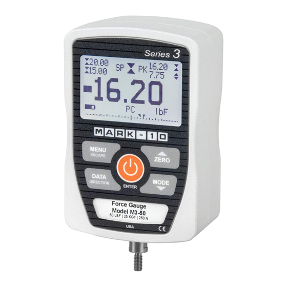
User’s Guide Thank you… Thank you for purchasing a Mark-10 Series 3 digital force gauge, designed for tension and compression force testing applications from 0.12 lbF to 500 lbF (0.5 N to 2,500 N) full scale. The Series 3 is an essential component of a force testing system, typically also comprising a test stand, grips, and data collection software. -
Page 3: Overview
Series 3 Digital Force Gauges User’s Guide 1 OVERVIEW 1.1 List of included items Part No. M3-012 – M3-50 – M3-200 – Qty. M3-20 M3-100 M3-500 Description 12-1049 12-1049 12-1049 Carrying Case AC1030 / AC1030 / AC1030 / AC adapter body with US, EU, or UK prong... -
Page 4: Power
Series 3 Digital Force Gauges User’s Guide accumulate in the sample during testing. Extra bodily protection should be worn if a destructive failure of a test sample is possible. 6. In certain applications, such as the testing of brittle samples that can shatter, or other applications that could lead to a hazardous situation, it is strongly recommended that a machine guarding system be employed to protect the operator and others in the vicinity from shards or debris. -
Page 5: Setup
These holes are designed to accommodate screws in order to hold the gauge in place (Mark-10 test stands include a set of thumb screws for gauge mounting). The screws must not be used for load bearing purposes. Failure to use a dowel pin properly can result in a hazardous situation. -
Page 6: Home Screen And Controls
3.2 Installing the USB driver If communicating via USB, install the USB driver provided on the Resource CD. Installation instructions may also be found on the CD or may be downloaded from www.mark-10.com. Caution! Install the USB driver before physically connecting the gauge to a PC with the USB cable. - Page 7 Series 3 Digital Force Gauges User’s Guide lbF – Pound-force kgF – Kilogram-force gF – Gram-force N – Newton Note: not all gauge capacities measure in all the above units. Refer to the capacity / resolution table in the Specifications section for details. Mode The current measurement mode.
-
Page 8: Operating Modes
Series 3 Digital Force Gauges User’s Guide For parameters requiring the input of a numerical value, use the UP and DOWN keys to increment or decrement the value. Press and hold either key to auto-increment at a gradually increasing rate. When the desired value has been reached, press ENTER to save the change and revert back to the sub-menu item, or press ESCAPE to revert back to the sub-menu item without saving. -
Page 9: Set Point Indicators
Series 3 Digital Force Gauges User’s Guide To access digital filter settings, select Filters from the menu. The display appears as follows: DIGITAL FILTERS (1 = Fastest) Current Reading Displayed Reading Two filters are available: Current Reading – Applies to the peak capture rate of the instrument. Displayed Reading –... -
Page 10: Communications And Outputs
Series 3 Digital Force Gauges User’s Guide – the displayed value is greater than the upper force limit (NO GO HIGH) – the displayed value is between the limits (GO) – the displayed value is less than the lower force limit (NO GO LOW) Note: Set point indicators reference the displayed reading, not necessarily the current live load. -
Page 11: Calibration
Series 3 Digital Force Gauges User’s Guide Selection Description Numeric + Units Output format includes the value and unit of measure. Compression values have positive polarity, tension values have negative polarity. Numeric Only Output format includes the value only. Polarity same as above. Invert Polarity Compression values have negative polarity, tension values have positive polarity. - Page 12 Series 3 Digital Force Gauges User’s Guide CALIBRATION To invert the display, press the DIRECTION button, then press ENTER. 2. Press DIRECTION to invert the display, if desired. ENTER to continue. The display appears as follows: CALIBRATION Enter # cal points (1 to 10) Compression: Tension:...
- Page 13 Series 3 Digital Force Gauges User’s Guide CALIBRATION OFFSET Please wait… CALIBRATION CALIBRATION OFFSET OFFSET Sensor passed Sensor failed Analog passed Analog failed If failed: 6. The following screen appears after the offsets have been calculated: CALIBRATION COMPRESSION Attach necessary weight fixtures, then press ENTER.
- Page 14 Series 3 Digital Force Gauges User’s Guide CALIBRATION COMPRESSION Ensure no load, then press ZERO. Remove the load applied in Step 8, leave the fixtures in place, then press ZERO. 10. The display appears as follows: CALIBRATION COMPRESSION Apply load 1 OF 5 Enter load: 2.00 lbF...
- Page 15 Series 3 Digital Force Gauges User’s Guide CALIBRATION COMPLETE Save & exit Exit w/o saving To save the calibration information, select “Save & exit”. To exit without saving the data select “Exit without saving”. 14. Any errors are reported by the following screens: CALIBRATION Units must be kgF.
-
Page 16: Other Settings
Series 3 Digital Force Gauges User’s Guide 11 OTHER SETTINGS 11.1 Automatic Shutoff The gauge may be configured to automatically power off following a period of inactivity while on battery power. Inactivity is defined as the absence of any key presses or load changes of 100 counts or less. To access these settings, select Automatic Shutoff from the menu. - Page 17 Series 3 Digital Force Gauges User’s Guide LCD CONTRAST Set Contrast Press ENTER to modify the contrast. Select a value from 0 to 25, 25 producing the most contrast. 11.4 Tones Audible tones can be enabled for all key presses and alerts, such as overload, set point value reached, etc.
-
Page 18: Specifications
N (depending on model) Safe overload: 200% of full scale (display shows “OVER” at 110% and above) M3-012 – M3-100: 0.7 lb [0.33 kg] Weight (gauge only): M3-200 – M3-500: 0.9 lb [0.41 kg] Carrying case, chisel, cone, V-groove, hook, flat, extension rod, AC adapter, battery, USB... - Page 19 Initial Mode Real Time Units 12.3 Capacity, Resolution & Load Cell Deflection Load Cell Deflection Model in [mm] 0.005 [0.13] M3-012 0.12 x 0.0001 50 x 0.05 0.5 x 0.0005 0.010 [0.25] M3-025 0.25 x 0.0002 100 x 0.1 1 x 0.001 M3-05 0.5 x 0.0005...
- Page 20 Series 3 Digital Force Gauges User’s Guide 12.4 Dimensions IN [MM] Thread Flat M3-012 – M3-100 #10-32 UNF 5/16 [7.94] M3-200 – M3-500 5/16-18 UNC 5/16 [7.94] 1.800.561.8187 GlobalTestSupply information@itm.com www. www. .com .com Find Quality Products Online at: sales@GlobalTestSupply.com...
- Page 21 Series 3 Digital Force Gauges User’s Guide Mark-10 Corporation has been an innovator in the force and torque measurement fields since 1979. We strive to achieve 100% customer satisfaction through excellence in product design, manufacturing and customer support. In addition to our standard line of products we can provide modifications and custom designs for OEM applications.
Need help?
Do you have a question about the M3-012 and is the answer not in the manual?
Questions and answers