Table of Contents
Advertisement
Quick Links
ACTUAL PRODUCT MAY NOT APPEAR EXACTLY AS SHOWN
WARNING
Do not operate or service this product unless you have
read and fully understand the entire contents of this
manual. Failure to do so may result in bodily injury or
death.
STARTING FROM AUGUST 14, 2020 / SERIAL # 467201
OWNER'S MANUAL
BLUE GIANT INTERLOCK CHOCK™
ISSUE DATE: OCTOBER 20, 2021 REV. 1.2.1 (PART # 038-1125E)
Advertisement
Table of Contents

Related Manuals for Blue Giant INTERLOCK CHOCK


Summary of Contents for Blue Giant INTERLOCK CHOCK
- Page 1 OWNER’S MANUAL BLUE GIANT INTERLOCK CHOCK™ ACTUAL PRODUCT MAY NOT APPEAR EXACTLY AS SHOWN WARNING Do not operate or service this product unless you have read and fully understand the entire contents of this manual. Failure to do so may result in bodily injury or death.
-
Page 3: Table Of Contents
INTERLOCK CHOCK — OWNER’S MANUAL Table of Contents Table of Contents 1.0 ABOUT THE INTERLOCK CHOCK 1.0 ABOUT THE INTERLOCK CHOCK 1.1 OWNER’S PURCHASE RECORD 1.1 OWNER’S PURCHASE RECORD 2.0 INTRODUCTION 2.0 INTRODUCTION 2.1 WARRANTY INFORMATION 2.1 WARRANTY INFORMATION 2.2 EXCLUSION OF LIABILITY 2.2 EXCLUSION OF LIABILITY... - Page 4 INTERLOCK CHOCK — OWNER’S MANUAL ISSUE DATE: OCTOBER 20, 2021 REV. 1.2.1 (PART # 038-1125E)
-
Page 5: About The Interlock Chock
Concurrent with a continuing product improvement program, specifications are subject to change without notice (See “2.1 WARRANTY INFORMATION” on page 6). Please contact the your Blue Giant Dealer for latest information. Some features illustrated may be optional in certain market areas. -
Page 6: Introduction
INTRODUCTION The following is a quick reference to important procedures that must be followed while using the Interlock Chock . It is not intended to cover, or suggest that it does cover, all procedures necessary to ensure safe operation. All operators should be aware of and abide by all workplace safety regulations applicable to the operation of the Interlock Chock . -
Page 7: Manufacturer's Note
Unless specifically agreed to in writing by Blue Giant Equipment Corporation at the time of order (and prior to manufacture), all Blue Giant Interlock Chock is sold as a complete offering and must not be altered or added to in any manner (which includes configuration and function) without written permission from an authorized manufacturer’s representative. - Page 8 INTERLOCK CHOCK — OWNER’S MANUAL If, at the request of the owner, Blue Giant does not supply all or some of the Interlock Chock power unit and/or control panel components, the owner shall assume responsibility for any and all operational and safety issues associated with the resulting configuration.
-
Page 9: Safety Message Color Identification
CAUTION • Only trained personnel should operate or service this equipment. • Do not operate the Interlock Chock until the transport vehicle is parked against the dock bumpers. • Always park the Interlock Chock after use. • Conduct routine inspections and maintenance. Failure to do so could cause equipment damage and or personal injury. - Page 10 Always clean up dry and liquid spills immediately after they occur. • Always maintain proper lighting in the work area. • If a pro cedure is not clearly defined in this manual, contact your Blue Giant Dealer. ISSUE DATE: OCTOBER 20, 2021 REV. 1.2.1 (PART # 038-1125E)
-
Page 11: Lockout / Tagout Procedure And Rules
The machine or equipment power supply shall be locked in the OFF position or disconnected from the energy source. Blue Giant strongly recommends that only OSHA-approved and/or local jurisdiction lockout devices and procedures be utilized. The energy isolating device must bear a prominent warning tag indicating that work is being done on the equipment and the name of the authorized employee responsible for the lockout. -
Page 12: Electrostatic Sensitive Device Protection Policy
FOR HANDLING ELECTROSTATIC SENSITIVE DEVICES DO NOT DISCARD. Any components shipped back to Blue Giant must be in their original packaging (along with completed RGA form taped to the OUTSIDE of the static bag) or warranty may be voided. 038-850E Prior to handling PCBs, wear a static grounding wrist strap and clip it to an electrical ground. -
Page 13: Independent Type Control Station
5.1 PUSH BUTTON CONTROLS PUSH BUTTON CONTROLS Controls one individual vehicle Interlock Chock only, equipped with touch buttons, inside forklift operator traffic lights, operator menu screen, and keypad for coded features. Controls one individual vehicle wheel chock only, equipped with touch buttons, inside forklift operator traffic lights, operator menu screen, and keypad for coded features. -
Page 14: Button Function
INTERLOCK CHOCK — OWNER’S MANUAL 5.2 BUTTON FUNCTION BUTTON FUNCTION When touching any of the function buttons or keypad, use the ball of the finger. Pressure not required to operate buttons. The control station’s unique touch sensors detect the proximity of the dock operator’s finger. -
Page 15: Operating Instructions
Follow the safe operating instructions to ensure personnel, load, and equipment safety. WARNING • Do not operate the Interlock Chock unless you have been trained and authorized to do so, and have read and understood all of the safety information and instructions contained in this manual. •... - Page 16 INTERLOCK CHOCK — OWNER’S MANUAL Close door completely. Blue Genius Control Panel illuminates solid RED. GOLD BG MENU READY TO RELEASE ES C DISPLAY SE L SCREEN En ter Do No t READY TO RELEASE PLATINUM BG Ca uti on...
-
Page 17: Maintenance
The PMP will provide an opportunity to make a thorough inspection of the safety and operating condition of the Interlock Chock . Necessary adjustments and repairs can be done during the PMP , which will increase the life of components and reduce unscheduled downtime. -
Page 18: Daily Maintenance Procedures (Dmp) Checklist
SERIAL #: DOOR #: Forward this checklist to the person responsible for Interlock Chock maintenance. See “Owner’s Purchase Record” for Date in Service. INSTRUCTIONS: Indicate “OK for USE” with a check mark in the appropriate box of each inspection point. Indicate “NOT OK for USE”... -
Page 19: Recommended Spare Parts
INTERLOCK CHOCK — OWNER’S MANUAL 8.0 RECOMMENDED SPARE PARTS RECOMMENDED SPARE PARTS STANDARD OPERATIONAL COMPONENTS ITEM PART # DESCRIPTION QTY REQ’D 2009848 Toothed Flange 2012832 Chock - Machined 012-703 Whip 2014943 Cradle 012-702 Flex Strain Relief Connector 2016909 Cable Clamp 011-205 Headscrew #10-24, 7/8in. - Page 20 INTERLOCK CHOCK — OWNER’S MANUAL STANDARD OPERATIONAL COMPONENTS ITEM PART # DESCRIPTION QTY REQ’D BGRM001-ITC485 I/O Board, LED board, and Sensors 2014934 I/O Module with Handle Weldment 2015246 Side Cover 026-M12-M6HD Cable, M12-4, 6M, Male leads 025-005 CONNECTOR 1/2” CORD GRIP - 90 DEGREE...
-
Page 21: Decal Identification And Location
INTERLOCK CHOCK — OWNER’S MANUAL 9.0 DECAL IDENTIFICATION AND LOCATION DECAL IDENTIFICATION AND LOCATION These labels inform operators and personnel about hazardous areas on and around the Interlock Chock. CAUTION SHARP EDGES WATCH YOUR HANDS AND FEET SHARP HAZARD 038-1135E... - Page 22 Only for the Blue Giant Interlock Chock ™ PLACE WHEEL CHOCK Standard and end loading follow the same procedure. Once the vehicle driver has placed the Interlock Chock, the Blue Genius Control Panel flashes AMBER. ES C ES C Fully open the dock door.
- Page 23 INTERLOCK CHOCK — OWNER’S MANUAL MANDATORY WHEELS MUST BE CHOCKED WARNING IF ALARM SOUNDS AND WHEEL CHOCK FLASHES RED ENSURE CHOCK IS ENGAGED 038-1139E ISSUE DATE: OCTOBER 20, 2021 REV. 1.2.1 (PART # 038-1125E)
-
Page 24: Equipment Component Illustrations
™ PLACE WHEEL CHOCK Standard and end loading follow the same procedure. Once the vehicle driver has placed the Interlock Chock, the Blue Genius Control Panel flashes AMBER. Fully open the dock door. While the door is opening, Blue Genius Control Panel will illuminate WHEELS solid RED. -
Page 25: General Dimensions
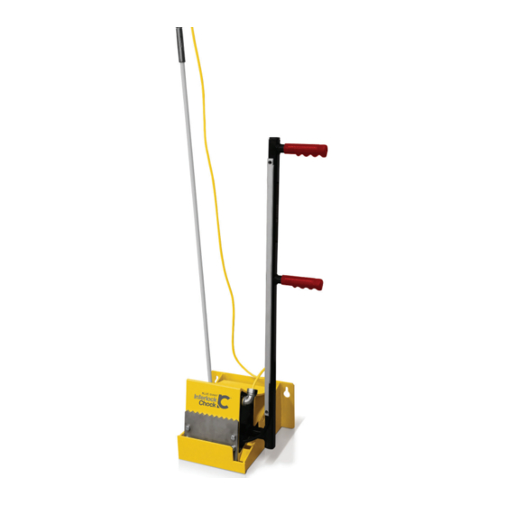
INTERLOCK CHOCK — OWNER’S MANUAL 10.2 10.2 GENERAL DIMENSIONS GENERAL DIMENSIONS This section describes the length and height of the Interlock Chock components. ITEM DESCRIPTION 11 3/4in. (298 mm) 7in. (178 mm) 7 7/8in. (200 mm) 33 9/32in (845 mm) 100 3/4in. -
Page 26: Controls
INTERLOCK CHOCK — OWNER’S MANUAL 10.3 10.3 CONTROLS CONTROLS This section depicts the Blue Genius Control Panel. NOTE: Actual product may not appear exactly as shown. Wiring Diagram Enclosed Fuse Holder 3 Fuse Holder 1 Fuse Holder 2 CONTROL ASSEMBLY... -
Page 27: Junction Box W/Remote I/O
INTERLOCK CHOCK — OWNER’S MANUAL 10.4 10.4 JUNCTION BOX W/REMOTE I/O JUNCTION BOX W/REMOTE I/O This section depicts the junction box connecting the Blue Genius Control Panel to the wiring external to the building. JUNCTION BOX ASSEMBLY ITEM PART #... - Page 28 INTERLOCK CHOCK — OWNER’S MANUAL 10.5 10.5 JUNCTION BOX ASSEMBLY JUNCTION BOX ASSEMBLY This section depicts the exterior junction box that connects the Interlock Chock and Exterior Traffic Lights to the wiring from the Blue Genius Control Panel JUNCTION BOX ASSEMBLY ITEM #...
-
Page 29: Dock Interlock Sensor
INTERLOCK CHOCK — OWNER’S MANUAL 10.6 10.6 DOCK INTERLOCK SENSOR DOCK INTERLOCK SENSOR This section depicts the door interlock sensor and the mounting bracket. Sensor Part # 028-206 Bracket Part # 21-002154 Dock interlock sensor (home/lip sensor). The sensor ties the sequence of wheel chock to the dock leveler operation. Loading dock safety is improved with accurate operation sequence. -
Page 30: Exterior Driver Traffic Light
INTERLOCK CHOCK — OWNER’S MANUAL 11.0 11.0 EXTERIOR DRIVER TRAFFIC LIGHT EXTERIOR DRIVER TRAFFIC LIGHT The exterior traffic lights improve loading dock safety. 5" (127 mm) 4 3/8" (111 mm) Ø 5/16" x 4 Exterior driver traffic light, part # 032-806. -
Page 31: Exterior Driver Warning Sign
INTERLOCK CHOCK — OWNER’S MANUAL 11.1 11.1 EXTERIOR DRIVER WARNING SIGN EXTERIOR DRIVER WARNING SIGN The exterior warning sign for drivers improves loading dock safety. ¼" (6 mm) 11.75" (298 mm) 3/8" (10 mm) Exterior driver warning sign, part # 038-225 (French 038-225F / Spanish 038-225S / Portuguese 038-225P) 3/8"... -
Page 32: Exterior Operating Instruction Placard
INTERLOCK CHOCK — OWNER’S MANUAL 11.2 11.2 EXTERIOR OPERATING INSTRUCTION PLACARD EXTERIOR OPERATING INSTRUCTION PLACARD The Exterior Operation Placard (part # 038-1139E/F) for outside dock workers or drivers. MANDATORY WHEELS MUST BE CHOCKED WARNING IF ALARM SOUNDS AND WHEEL CHOCK... -
Page 33: Interior Operating Instruction Placard
™ PLACE WHEEL CHOCK Standard and end loading follow the same procedure. Once the vehicle driver has placed the Interlock Chock, the Blue Genius Control Panel flashes AMBER. Fully open the dock door. While the door is opening, Blue Genius Control Panel will illuminate solid RED. -
Page 34: Troubleshooting
Use this section to help diagnose issues if the Interlock Chock is not operating as specified. DANGER • Failure to properly secure the Interlock Chock deck prior to working underneath it may result in bodily injury, or death. WARNING •... -
Page 35: Wiring Diagrams
INTERLOCK CHOCK — OWNER’S MANUAL 13.0 13.0 WIRING DIAGRAMS WIRING DIAGRAMS NOTICE The following wiring diagrams are sample configurations only. Wiring diagrams specific to your needs will be provided inside the control panel and/or as part of your submittal package. - Page 36 INTERLOCK CHOCK — OWNER’S MANUAL NOTE: Refer to both wiring diagrams for the two door sensor wiring arrangements. WHITE GREEN DRAIN GREEN BLACK DRAIN WHITE BLACK ISSUE DATE: OCTOBER 20, 2021 REV. 1.2.1 (PART # 038-1125E)
- Page 37 INTERLOCK CHOCK — OWNER’S MANUAL ISSUE DATE: OCTOBER 20, 2021 REV. 1.2.1 (PART # 038-1125E)
- Page 38 INTERLOCK CHOCK — OWNER’S MANUAL ISSUE DATE: OCTOBER 20, 2021 REV. 1.2.1 (PART # 038-1125E)
- Page 39 INTERLOCK CHOCK — OWNER’S MANUAL ISSUE DATE: OCTOBER 20, 2021 REV. 1.2.1 (PART # 038-1125E)
- Page 40 Corporate 410 Admiral Blvd USA 6350 Burnt Poplar Road Mississauga, ON, Canada L5T 2N6 Greensboro, NC 27409 t 905.457.3900 f 905.457.2313 www.bluegiant.com If calling within North America: t 1.800.872.2583 f 1.888.378.5781 © Copyright Blue Giant Equipment Corporation 2021...
Need help?
Do you have a question about the INTERLOCK CHOCK and is the answer not in the manual?
Questions and answers