Table of Contents
Advertisement
Quick Links
Advertisement
Table of Contents

Related Manuals for Xylem Multi 3620 IDS


Summary of Contents for Xylem Multi 3620 IDS
- Page 1 OPERATING MANUAL ba77169d06 10/2021 Multi 3620 IDS DIGITAL METER FOR IDS SENSORS...
- Page 2 Multi 3620 IDS Copyright © 2021 Xylem Analytics Germany GmbH Printed in Germany. ba77169d06 10/2021...
-
Page 3: Table Of Contents
Contents Multi 3620 IDS - Contents Overview ......... . 7 MeterMulti 3620 IDS . - Page 4 Contents Multi 3620 IDS 4.5.1 Operating modes ......23 4.5.2 Measured value display ......23 4.5.3...
- Page 5 Multi 3620 IDS Contents standard) ....... . 59 8.3.4 Calibration data ....... 60 ®...
- Page 6 Contents Multi 3620 IDS 14 Maintenance, cleaning, disposal..... . 97 14.1 Maintenance ........97 14.1.1...
-
Page 7: Overview
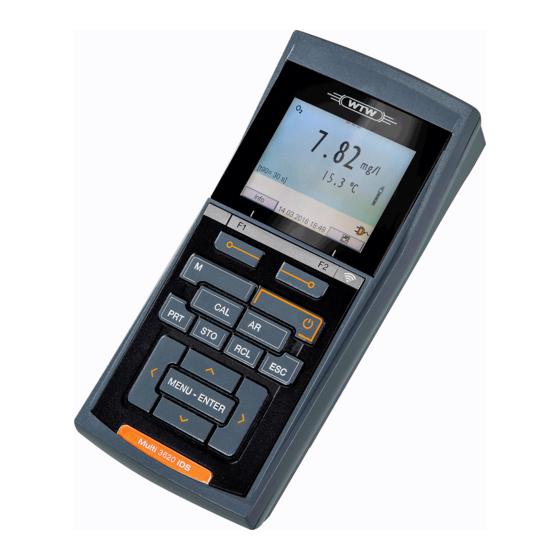
Multi 3620 IDS Overview Overview MeterMulti 3620 IDS The compact, digital precision meter Multi 3620 IDS enables you to carry out pH measurements, ORP measurements, conductivity measurements, dis- solved oxygen (D.O.) measurements and turbidity measurements quickly and reliably. The Multi 3620 IDS provides the maximum degree of operating comfort, reli- ability and measuring certainty for all applications. -
Page 8: Sensors
® head connectors (variant P) or OxiTop -IDS measuring heads can be wire- lessly connected to your Multi 3620 IDS. Further information on the wireless operation of IDS sensors: Web resources Operating manual of the IDS WLM System. -
Page 9: Automatic Sensor Recognition
to hide menus automatically that do not concern this sensor To be able to use the automatic sensor recognition, a meter that supports the automatic sensor recognition (e.g. Multi 3620 IDS) and a digital IDS sensor are required. In digital IDS sensors, sensor data are stored that clearly identify the sensor. -
Page 10: Safety
Safety Multi 3620 IDS Safety Safety information 2.1.1 Safety information in the operating manual This operating manual provides important information on the safe operation of the meter. Read this operating manual thoroughly and make yourself familiar with the meter before putting it into operation or working with it. The operating manual must be kept in the vicinity of the meter so you can always find the infor- mation you need. -
Page 11: Safe Operation
Multi 3620 IDS Safety Safe operation 2.2.1 Authorized use The authorized use of the meter consists exclusively of the measurement of the pH, ORP, conductivity and dissolved oxygen in a laboratory environment. Only the operation and running of the meter according to the instructions and... -
Page 12: Commissioning
– detailed operating manual – software MultiLab Importer Power supply The Multi 3620 IDS is supplied with power in the following ways: Battery operation with NiMh rechargeable batteries Mains operation with the supplied power pack. The NiMh batteries are automatically charged while the power pack is con- nected. -
Page 13: Inserting The Rechargeable Batteries
Multi 3620 IDS Commissioning 3.3.1 Inserting the rechargeable batteries 1 Screws 2 Battery compartment Unscrew the two screws (1) on the underside of the meter. Open the battery compartment (2) on the underside of the meter. CAUTION Make sure that the poles of the rechargeable batteries are po- sitioned correctly. -
Page 14: Switch On The Meter
(104 °F) when the power pack is connected. Connect the plug of the power pack to the socket for the power pack on the Multi 3620 IDS. Connect the original power pack to an easily accessible power outlet. Charge the batteries completely prior to putting the meter into opera- tion for the first time. -
Page 15: Setting The Date And Time
Multi 3620 IDS Commissioning 3.3.4 Setting the date and time See section 4.5.5 ba77169d06 10/2021... -
Page 16: Operation
Operation Multi 3620 IDS Operation General operating principles 4.1.1 Keypad In this operating manual, keys are indicated by brackets <..> . <MENU/ENTER> The key symbol (e.g. ) generally indicates a short keystroke (under 2 sec) in this operating manual. A long keystroke (approx. 2 sec) is indi- <MENU/ENTER_>... -
Page 17: Display
Multi 3620 IDS Operation 4.1.2 Display Example (pH): AutoCal TEC HOLD AR 22.09.2009 08:00 Info 1 Status information (meter) 2 Status information (sensor) 3 Measured value 4 Measured parameter 5 Continuous measurement control (CMC function) 6 Channel display: Plug position of the sensor... -
Page 18: Connectors
(> SELV and > current circuit with current limiting). WTW IDS sensors and IDS adapters meet these requirements. 4.1.5 Channel display The Multi 3620 IDS administers the sensors connected and displays which sensor is plugged to which connection. ba77169d06 10/2021... -
Page 19: Sensor Info
Multi 3620 IDS Operation Info 1 Channel display: Display of the plug position for the relevant parameter The red bar indicates for each connected sensor to which plug posi- tion (channel) of the meter it is connected. 4.1.6 Sensor info You can display the current sensor data and sensor settings of a connected sensor at any time. -
Page 20: Display Of Several Sensors In The Measuring Mode
Operation Multi 3620 IDS Display further sensor data (settings) with [More]. SenTix 940 B092500013 25 °C Man. temperature: pH resolution 0.001 mV resolution Buffer Calibration interval Unit for slope mV/pH QSC: Software version 30.09.2012 08:00 4.1.7 Display of several sensors in the measuring mode... -
Page 21: Switching Off The Meter
Multi 3620 IDS Operation Info 30.09.2012 08:00 If the user administration function is activated, the Login dialog appears after the meter is switched on (see section 4.4). The user administration function is not active in the delivery condi- tion. The user administration is activated by the administrator via the PC software MultiLab User (see MultiLab User operating manual). - Page 22 Operation Multi 3620 IDS Login User name Admin Password #### Change password 30.09.2012 08:00 < >< > Using , select the menu item, User name and confirm with <MENU/ENTER> The user name is highlighted. < >< > <MENU/ ...
-
Page 23: Navigation
Multi 3620 IDS Operation < >< > Using , select the menu item, Change password and confirm <MENU/ENTER> with < >< > In the Password field, enter the old password with < >< > <MENU/ENTER> ... -
Page 24: Menus And Dialogs
Operation Multi 3620 IDS 4.5.3 Menus and dialogs The menus for settings and dialogs in procedures contain further subelements. < >< > The selection is done with the keys. The current selection is dis- played with a frame. -
Page 25: Navigation Example 1: Setting The Language
Multi 3620 IDS Operation Calibration record Calibration data storage Buffer: Single-point calibration: Calibration interval: Unit for slope: mV/pH ] 2.00 4.01 7.00 10.01 (25 °C) 30.09.2012 08:00 Messages Information is marked by the [ ] symbol. It cannot be selected. Example:... - Page 26 Operation Multi 3620 IDS Info 30.09.2012 08:00 <MENU/ENTER_> Open the Storage & config menu with The instrument is in the setting mode. Storage & config System Data storage 30.09.2012 08:00 < >< > Select the System submenu with The current selection is displayed with a frame.
-
Page 27: Example 2 On Navigation: Setting The Date And Time
Multi 3620 IDS Operation General Language: Deutsch Acoustic signal: Volume Illumination: Kontrast: 50 % Switchoff time: Temperature unit: °C Stability control: 30.09.2012 08:00 <MENU/ENTER> Open the setting mode for the Language with General Language: Deutsch Acoustic signal: Volume Illumination: Brightness:... - Page 28 Operation Multi 3620 IDS The date and time are reset to default after a fall of the supply volt- age (empty batteries). Setting the date, The date format can be switched from the display of day, month, year time and date format (dd.mm.yy) to the display of month, day, year (mm/dd/yy or mm.dd.yy).
-
Page 29: Ph Value
Measurement in grounded test samples Measurement with several sensors connected to one Multi 3620 IDS in one test sample Connect the IDS-pH sensor to the meter. The pH measuring window is displayed. -
Page 30: Measuring The Temperature
Multi 3620 IDS <MENU/ENTER> Using , activate the Stability control function manu- ally. The [AR] status indicator appears while the measured value is assessed as not stable. A progress bar is displayed and the display of the measured parameter flashes. -
Page 31: Ph Calibration
Multi 3620 IDS pH value Measurement of the temperature with the integrated temperature sensor of an IDS sensor. If the measured value is taken over from an IDS sensor, the status indi- ↑ cator [TP ] is displayed in the measurement window of the IDS-pH ↓... - Page 32 Multi 3620 IDS <CAL> Start the calibration with The calibration display for the first buffer appears (voltage display). 30.09.2012 08:00 Thoroughly rinse the IDS sensor with deionized water. Immerse the IDS-pH sensor in buffer solution 1. For measurements without temperature sensor (e.g.
- Page 33 Multi 3620 IDS pH value Continuing with two- Thoroughly rinse the IDS sensor with deionized water. point calibration Immerse the pH sensor in buffer solution 2. When measuring without temperature sensor: Measure the temperature of the buffer manually and enter it with <...
-
Page 34: Manual Calibration (Concal)
Multi 3620 IDS 30.09.2012 08:00 Wait for the measurement with stability control to be completed or ter- minate the stability control and take over the calibration value with <MENU/ENTER> The calibration display for the next buffer appears (voltage display). - Page 35 Multi 3620 IDS pH value ConCal 15.03.2014 08:00 Thoroughly rinse the IDS sensor with deionized water. Immerse the IDS-pH sensor in buffer solution 1. For measurements without temperature sensor (e.g. when using an IDS adapter Measure the temperature of the buffer manually and enter it with <...
- Page 36 Multi 3620 IDS ConCal 15.03.2014 08:00 Set the nominal buffer value for the measured temperature with < >< > <MENU/ENTER> Accept the calibration value with The calibration display for the next buffer appears (voltage display). If necessary, finish the calibration procedure as a single-point calibra- <M>...
- Page 37 Multi 3620 IDS pH value ConCal 15.03.2014 08:00 Set the nominal buffer value for the measured temperature with < >< > <MENU/ENTER> Accept the calibration value with The calibration display for the next buffer appears (voltage display). If necessary, finish the calibration procedure as a two-point calibration <M>...
-
Page 38: Calibration Points
Multi 3620 IDS Set the nominal buffer value for the measured temperature with < >< > <MENU/ENTER> Accept the calibration value with The calibration display for the next buffer appears (voltage display). <M> If necessary, use to finish the calibration. - Page 39 Multi 3620 IDS pH value Menu item Setting/func- Explanation tion Calibration / Displays the calibration records. Calibration data stor- age /Display Further options: Scroll through the calibration < >< > records with Output the displayed calibra- tion record to the interface with <PRT>...
-
Page 40: Continuous Measurement Control (Cmc Function)
Multi 3620 IDS Display Calibration Zero point Slope [mV/ record [mV] < -30 or ... -62 or Error Error > 30 ... -50 Perform error elimination according to chapter 15 W HAT TO DO IF For pH IDS sensors, you can optionally enable a more finely graded calibration evaluation (QSC) (see section 5.4). -
Page 41: Qsc Function (Sensor Quality Control)
Multi 3620 IDS pH value The following information is displayed: Info 30.09.2012 08:00 1 Currently measured pH value (needle) 2 Marking lines for all nominal buffer values used with the last valid cali- bration 3 Measuring range for which a valid calibration is available. Measured values in this range are suitable for documentation. - Page 42 Multi 3620 IDS sensor evaluation by means of a pointer. 01.02.2014 08:00 Info 1 QSC scale The double arrow on the QSC scale indicates the current sensor evaluation In the printout, the sensor evaluation is quoted as a percentage (1-100).
- Page 43 Multi 3620 IDS pH value As soon as the QSC function was enabled for an IDS sensor, it is not possible to return to the sensor evaluation with the sensor sym- bol for this sensor. Carrying out a QSC <MENU/ENTER>...
- Page 44 Multi 3620 IDS sor evaluation. 01.02.2014 08:00 Info 1 QSC scale The double arrow on the QSC scale indicates the current sensor evaluation You can carry out QSC control calibrations at greater intervals than normal cali- brations. A QSC control calibration can, e.g. be useful if the sensor evaluation noticeably changed (after some normal calibrations).
-
Page 45: Orp
Measurement in grounded test samples Measurement with several sensors connected to one Multi 3620 IDS in one test sample Connect the IDS-ORP sensor to the meter. The ORP measuring window is displayed. -
Page 46: Measuring The Temperature
Multi 3620 IDS menu. <AR> Freeze the measured value with The [HOLD] status indicator is displayed. <MENU/ENTER> Using , activate the Stability control function manu- ally. The [AR] status indicator appears while the measured value is assessed as not stable. A progress bar is displayed and the display of the measured parameter flashes. -
Page 47: Orp Calibration
Multi 3620 IDS mode: Temperature Resolution of the Mode sensor temp. display 0.1 °C Automatic with temperature sensor 1 °C Manual ORP calibration ORP electrodes are not calibrated. You can, however, check ORP electrodes by measuring the ORP of a test solution and comparing the value with the nominal value. -
Page 48: Dissolved Oxygen
Measurement in grounded test samples Measurement with several sensors connected to one Multi 3620 IDS in one test sample Connect the D.O. sensor to the meter. The D.O. measuring screen is displayed. - Page 49 Multi 3620 IDS Dissolved oxygen Freezing the mea- With the HOLD function, you can freeze the current measured value. The dis- sured value (HOLD played measured value stops changing until you switch the HOLD function off. function) <AR> Freeze the measured value with The [HOLD] status indicator is displayed.
-
Page 50: Measuring The Temperature
Dissolved oxygen Multi 3620 IDS Criteria for a stable The Stability control function checks whether the measured values are stable measured value within the monitored time interval. Measured Time interval Stability in the time inter- parameter D.O. concentra- 20 seconds Δ... -
Page 51: Evaluation
Multi 3620 IDS Dissolved oxygen Stability control The Stability control function (AutoRead) is automatically activated for the ® (AutoRead) Check. ® Proceed as follows to carry out the FDO Check procedure: Connect the D.O. sensor to the meter. Place the D.O. sensor in the check and storage beaker. -
Page 52: Calibration
Dissolved oxygen Multi 3620 IDS Example: – Required accuracy: ± 2 %. – In water vapor-saturated air or air-saturated water, the nominal value for the relative D.O. saturation (abbreviated: saturation) is 100 %. – Therefore, the validity scope is 98 ... 102 % –... -
Page 53: Calibration Data
Multi 3620 IDS Dissolved oxygen <CAL> Start the calibration with The last calibration data (relative slope) is displayed. 15.03.2014 08:00 <MENU/ENTER> Start the measurement with The measured value is checked for stability (stability control). The [AR] status indicator is displayed. The measured parameter flashes. - Page 54 Dissolved oxygen Multi 3620 IDS Menu item Setting/func- Explanation tion Calibration / Displays the calibration records. Calibration data stor- age / Display Further options: Scroll through the calibration < >< > records with Output the displayed calibra- tion record to the interface with <PRT>...
- Page 55 Multi 3620 IDS Dissolved oxygen Calibration record Multi 3620 IDS (USB output) Ser. no. 10139695 CALIBRATION Ox Calibration date 15.03.2016 16:13:33 FDO 925 Ser. no. 10146858 SC-FDO 925 10158765 Relative slope 0.98 Sensor ba77169d06 10/2021...
-
Page 56: Conductivity
Measurement in grounded test samples Measurement with several sensors connected to one Multi 3620 IDS in one test sample Connect an IDS conductivity sensor to the meter. The conductivity measuring window is displayed. - Page 57 Multi 3620 IDS Conductivity If the HOLD function is active, you can, e.g. start a manual mea- surement with stability control. <AR> Release the frozen measured value again with The HOLD function is switched off. The [HOLD] status display disappears.
-
Page 58: Measuring The Temperature
Conductivity Multi 3620 IDS within the monitored time interval. Measured Time interval Stability in the time interval parameter Conductivity ϰ 10 seconds Δ : better than 1.0% of measured value Temperature 15 seconds Δ : better than 0.5 °C The minimum duration until a measured value is assessed as stable is the mon- itored time interval. -
Page 59: Calibration
Multi 3620 IDS Conductivity Test sample Temperature compensation Display indica- Other aque- ous solutions Set linear temperature coefficient 0.001 ... 10.000 %/K Salinity (sea- Automatic nLF according to IOT Sal, nLF water) (International Oceanographic Tables) Calibration 8.3.1 Why calibrate? Aging slightly changes the cell constant, e.g. due to coatings. As a result, an inexact measured value is displayed. - Page 60 Conductivity Multi 3620 IDS <CAL> Start the calibration with The cell constant that was calibrated last is displayed. 30.09.2012 08:00 Immerse the IDS conductivity sensor in the control standard solution, 0.01 mol/l KCI. <MENU/ENTER> Start the measurement with The measured value is checked for stability (stability control).
- Page 61 Multi 3620 IDS Conductivity Menu item Setting/func- Explanation tion Calibration / Displays the calibration records. Calibration data storage / Display Further options: Scroll through the calibration < >< > records with Output the displayed calibration record to the interface with <PRT>...
- Page 62 Conductivity Multi 3620 IDS Calibration record Multi 3620 IDS (USB output) Ser. no. 09250023 CALIBRATION Cond Calibration date 15.03.2016 16:13:33 TetraCon 925 Ser. no. 09250033 Cell constant 0.476 1/cm 25.0 °C Sensor ba77169d06 10/2021...
- Page 63 Measurement in grounded test samples Measurement with several sensors connected to one Multi 3620 IDS in one test sample Preparatory activi- Perform the following preparatory activities when you want to measure: ties ...
- Page 64 ® Turbidity measurement (VisoTurb 900-P) Multi 3620 IDS Info 30.09.2012 08:00 <M> Selecting the You can switch between the following displays with displayed Turbidity [FNU] measured parameter Turbidity [NTU] Freezing the mea- With the HOLD function, you can freeze the current measured value. The dis- sured value (HOLD played measured value stops changing until you switch the HOLD function off.
- Page 65 ® Multi 3620 IDS Turbidity measurement (VisoTurb 900-P) <MENU/ENTER> Using , activate the Stability control function manu- ally. The [AR] status indicator appears while the measured value is assessed as not stable. A progress bar is displayed and the display of the measured parameter flashes.
- Page 66 ® Turbidity measurement (VisoTurb 900-P) Multi 3620 IDS 9.2.3 Calibration standards Calibrate with 1 to 3 turbidity standard solutions. The standard solutions must be selected in the following order. Standard solution Range (FNU/NTU) 0.0 ... 1.0 5.0 ... 200.0 200.0 ... 4000.0 The turbidity expected in the measurement dictates the number and selection of the standards.
- Page 67 ® Multi 3620 IDS Turbidity measurement (VisoTurb 900-P) Standard 0.0 FNU 15.09.2014 08:00 Thoroughly rinse the turbidity sensor with distilled water and dry it with a lint-free cloth. Immerse the turbidity sensor in the test sample at an angle. Position the turbidity sensor in the measuring vessel.
- Page 68 ® Turbidity measurement (VisoTurb 900-P) Multi 3620 IDS Standard 1010.0 FNU 15.09.2014 08:00 If necessary, terminate the calibration as a two-point calibration with <M> The new calibration values are displayed. Continue with three-point calibration. Continuing with Repeat the steps 11 to 15 with the third standard solution. The new calibration three-point calibra- values are displayed after the last calibration step was completed.
- Page 69 ® Multi 3620 IDS Turbidity measurement (VisoTurb 900-P) Menu item Setting/ Explanation function Calibration / Displays the calibration record. Calibration data storage / Display Further options: Scroll through the calibration < >< > records with Output the displayed calibration record to the interface with <PRT>...
- Page 70 -IDS measuring heads) Multi 3620 IDS ® BOD measurement (OxiTop -IDS measuring heads) Meters of the series MultiLine Multi 3620 IDS can be wirelessly connected to ® the OxiTop -IDS measuring heads. ® The OxiTop -IDS measuring heads in conjunction with a Multi 3620 IDS meter ®...
- Page 71 Multi 3620 IDS Settings Settings 11.1 pH measurement settings 11.1.1 Settings for pH measurements The settings are made in the menu for calibration and measurement settings of the pH/ORP measurement. To open the settings, display the required mea- <MENU/ sured parameter in the measured value display and press the ENTER>...
- Page 72 Settings Multi 3620 IDS Menu item Possible Explanation setting QSC / Control calibra- Starts the control calibration with QSC buffers. This menu item is only available if an initial calibration was tion carried out with the connected IDS sensor. Entry of the manually determined temperature.
- Page 73 Multi 3620 IDS Settings Buffer set * pH val- 1.000 20 °C Merck 2 * 6.000 8.000 13.000 4.660 20 °C Merck 3 * 6.880 9.220 2.000 20 °C Merck 4 * 4.000 7.000 10.000 4.010 25 °C Merck 5 * 7.000...
- Page 74 Settings Multi 3620 IDS Buffer set * pH val- 4.005 25 °C Beckman * 7.005 10.013 4.005 25 °C Hamilton Duracal * 7.002 10.013 3.996 25 °C Precisa * 7.003 8.999 Reagecon TEC * 2.000 25 °C 4.010 7.000 10.000 Reagecon 20 * 2.000...
- Page 75 Multi 3620 IDS Settings To ensure the high measuring accuracy of the measuring system, calibrate after the calibration interval has expired. Setting the calibra- The calibration interval is set to 7 days (d7) in the factory. tion interval You can change the interval (1 ... 999 days): <MENU/ENTER>...
- Page 76 Settings Multi 3620 IDS <M> ing the settings, switch to the measured value display with Menu item Possible Explanation setting Calibration / Displays the calibration record of the last calibration. Calibration record Calibration / Displays the last calibration records (max. 10)
- Page 77 Multi 3620 IDS Settings Menu item Possible Explanation setting Salinity or salinity equivalent for the Salinity 0.0 ... 70.0 salt content correction. This menu item is only available if the automatic salt content correction is switched off and the manual salt con- tent correction is switched on.
- Page 78 Settings Multi 3620 IDS bold Default settings are printed in Setting Menu item Possible Explanation menuTetraCon 925 setting Calibration / Displays the calibration record of the last calibration. Calibration record Calibration / Displays the last calibration records (max. 10) Calibration data...
- Page 79 Multi 3620 IDS Settings Menu item Possible Explanation setting Temp. comp. (TC) / Reference temperature 20 °C This setting is only available for the Reference temp. 25 °C measured parameters, ϰ and ρ. Factor for TDS value TDS factor 0.40 ... 1.00...
- Page 80 Settings Multi 3620 IDS bold tings are printed in Setting menu of the Menu item Possible Explanation ® setting VisoTurb 900-P Calibration / Displays the calibration record of the last calibration. Calibration record Calibration / Displays the last calibration records (max.
- Page 81 Top set management Resets the OxiTop set management to the default values.For details, see Com- plementary operating manual ® OxiTop -IDS (/B) Multi 3620 IDS ® wireless operation of OxiTop -IDS (/B) measuring heads System / Reset Resets the system settings to the default values.
- Page 82 This menu contains all functions to display, edit and erase stored measured values. Detailed information on the memory functions of the Multi 3620 IDS is given in section 12. 11.6.3 Automatic Stability control The automatic Stability control (AutoRead) function continuously checks the stability of the measurement signal.
- Page 83 Multi 3620 IDS Settings 11.7 Reset You can reset (initialize) all sensor settings and sensor-independent settings separately from each other. 11.7.1 Resetting the measurement settings The calibration data are reset to the default settings together with the measuring parameters. Recalibrate after performing a reset.
- Page 84 Settings Multi 3620 IDS with the Reset function: Setting Default settings Calibration interval 180 d Check interval 60 d Measured parameter D.O. concentration Relative slope (S 1,00 Salinity (value) Salinity (function) The sensor settings are reset under the Reset menu item in the menu for cali- bration and measurement settings.
- Page 85 Multi 3620 IDS Settings condition with the Reset function: Setting Default settings Calibration interval 30 d Measured parameter Auflösung The sensor settings are reset under the Reset menu item in the menu for cali- bration and measurement settings. To open the settings, display the required <MENU/...
- Page 86 Data memory Multi 3620 IDS Data memory You can transmit measured values (datasets) to the data memory: Manual storage (see section 12.1) Automatic storing at intervals (see section 12.2) Each data storing process transmits the current dataset to the interface at the same time.
- Page 87 Multi 3620 IDS Data memory Automatic data stor- ID number Interval 30 s Duration 180 min continue 0d03h00min 1d17h33mi 30.09.2012 08:00 1 Specified entire storing duration 2 Max. available storing duration 3 Graphical display of the memory usage Settings You can configure the automatic data storing function with the following...
- Page 88 Data memory Multi 3620 IDS play. 0d03h00min 03.04.2013 08:00 1 Remaining storing duration 2 Graphical display of the storing duration The active automatic data storing function can be recognized by the progress bar in the status line. The progress bar indicates the remaining storage dura- tion.
- Page 89 Multi 3620 IDS Data memory 12.3 Measurement data memory 12.3.1 Editing the measurement data memory The contents of the manual or automatic measurement data storage can be shown on the display. Each of the measurement data memories has a function to erase the entire contents.
- Page 90 Data memory Multi 3620 IDS Display presentation Manual data storage 3 of of a dataset 15.03.2016 11:24:16 number: 1 SenTix 940 B2023400856 pH 7.000 24.8 °C AR Sensor: +++ 30.09.2012 08:00 Sample printout 15.03.2014 09:56:20 Multi 3620 IDS Ser. no. 09250023 SenTix 940 Ser.
- Page 91 - 4 levels (+++, ++, +, -, or no evaluation) or - QSC (percentage) Memory locations The Multi 3620 IDS meter has two measurement data memories. The measured values recorded either manually or automatic are stored separately in individual measurement data memories.
- Page 92 Transmitting data Multi 3620 IDS Transmitting data The meter has the following interfaces: USB-B interface (USB Device) e.g. to connect a PC USB-A interface (USB Host), e.g. to connect a USB flash drive/USB printer Via the USB-B interface (USB Device) you can transmit data to a PC or printer and update the meter software.
- Page 93 Multi 3620 IDS Transmitting data Model Type Paper width Citizen CT-S281 Thermal transfer printer 58 mm Seiko Instruments Inc. DPU- Thermal transfer printer 58 mm S445* Star SP700 with USB inter- Matrix printer 76 mm face** DPU-S445 Recommended printer settings for...
- Page 94 Install the driver. Follow the Windows installation instructions as necessary. Connecting a PC Connect the Multi 3620 IDS to the PC via the USB-B interface (USB Device). The meter is listed as a virtual COM interface among the connections in the Windows instrument manager.
- Page 95 Multi 3620 IDS Transmitting data Adjusting the set- Set the same transmission data at the meter and PC: tings for the data Baud rate: to be selected in the range 1200 ... 19200 transmission Set at the PC only: –...
- Page 96 Transmitting data Multi 3620 IDS The following rule applies: With the exception of the menus, shortly <PRT> pressing the key generally outputs the display contents to the interface (displayed measured values, measuring datasets, calibration records). If there is a USB-B connection (USB Device), e.g.
- Page 97 Multi 3620 IDS Maintenance, cleaning, disposal Maintenance, cleaning, disposal 14.1 Maintenance 14.1.1 General maintenance activities The only maintenance activity required is replacing the batteries. See the relevant operating manuals of the IDS sensors for instructions on maintenance. 14.1.2 Replacing the rechargeable batteries...
- Page 98 Maintenance, cleaning, disposal Multi 3620 IDS Close the battery compartment (2) and tighten the screws (1). Charge the batteries completely prior to putting the meter into oper- ation for the first time. The charging process takes approx. 24 hours. Dispose of used batteries according to the local regulations of your country.
- Page 99 Multi 3620 IDS What to do if... What to do if... 15.1 General information Sensor symbol Cause Remedy flashes – Calibration interval expired – Recalibrate the measuring system Display Cause Remedy – Batteries almost empty – Charge the batteries (see section 3.3.2 C...
- Page 100 What to do if... Multi 3620 IDS Data transmission to Cause Remedy USB printer does not – The USB-B interface is con- – Disconnect the PC from the USB-B work nected to a PC interface – Connected USB printer does not –...
- Page 101 Multi 3620 IDS What to do if... Cause Remedy – Gel electrolyte dried out – Exchange IDS-pH sensor Error message, Cause Remedy Error IDS-pH sensor: – The values determined for zero – Recalibrate point and slope of the IDS-pH sensor are outside the allowed limits.
- Page 102 What to do if... Multi 3620 IDS Obviously incorrect Cause Remedy measured values IDS-pH sensor: – IDS-pH sensor unsuitable – Use suitable IDS sensor – Temperature difference – Adjust temperature of buffer or sam- between buffer and test sample ple solutions too great –...
-
Page 103: Turbidity
Multi 3620 IDS What to do if... More information and instructions on cleaning and exchange of sensors are given in the documentation of your sensor. 15.5 Turbidity Implausible turbidity Cause Remedy values – There are gas bubbles (e.g. air – Remove the gas bubbles, e.g. -
Page 104: Technical Data
Technical data Multi 3620 IDS Technical data 16.1 General data Dimensions Approx. 180 x 80 x 55 mm Weight Approx. 0.4 kg Mechanical structure Type of protection IP 67 Electrical safety Protective class Test certificates Ambient Storage - 25 °C ... + 65 °C... -
Page 105: Measuring Ranges, Resolution, Accuracy
Multi 3620 IDS Technical data USB interface (host) Type USB 2.0 USB-A (host), USB device Guidelines EU directive 2014/30/EU and norms used EN 61326-1 FCC Class A Meter safety EU directive 2014/35/EU EN 61010-1 IP protection class EN 60529 RoHS EU directive 2011/65/EU 16.2 Measuring ranges, resolution, accuracy... -
Page 106: Appendix: Firmware Update
the driver for the USB interface (see Internet or the CD-ROM enclosed to your meter) the USB cable (included in the scope of delivery of the Multi 3620 IDS). Install the downloaded firmware update on a PC. An update folder is created in the Windows start menu. -
Page 107: Firmware-Update For Ids Sensors And Ids Adapters
Multi 3620 IDS Appendix: Firmware update 17.2 Firmware-Update for IDS sensors and IDS adapters With the "Firmware Update" program and a PC you can update the firmware of an IDS sensor or an IDS adapter to the newest version. You can find available firmware update files on the Internet. -
Page 108: Glossary
Glossary Multi 3620 IDS Glossary Asymmetry see zero point Resolution Smallest difference between two measured values that can be dis- played by a meter. AutoRange Name of the automatic selection of the measuring range. Junction The junction is a porous body in the housing wall of reference elec- trodes or electrolyte bridges. - Page 109 Multi 3620 IDS Glossary Reset Restoring the original condition of all settings of a measuring system. Salinity The absolute salinity S of seawater corresponds to the relationship of the mass of dissolved salts to the mass of the solution (in g/Kg). In practice, this dimension cannot be measured directly.
- Page 110 Glossary Multi 3620 IDS ba77169d06 10/2021...
-
Page 111: Index
Multi 3620 IDS Verzeichnisse Index Automatic switch-off function ... 82 Initial commissioning ....12, 14 AutoRead ....49, 57, 64 Initialize . - Page 112 Verzeichnisse Multi 3620 IDS Temperature compensation ... 58 Temperature measurement Conductivity ..... 58 O2 .
- Page 114 Xylem also provides a leading portfolio of smart metering, network technologies and advanced analytics solutions for water, electric and gas utilities. In more than 150 countries, we have strong, long-standing relationships with customers who know us for our powerful combination of leading product brands and applications expertise with a strong focus on developing comprehensive, sustainable solutions.
Need help?
Do you have a question about the Multi 3620 IDS and is the answer not in the manual?
Questions and answers