Table of Contents
Advertisement
Quick Links
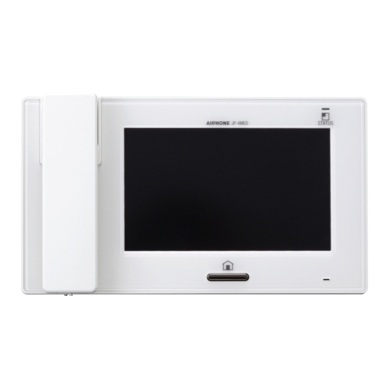
JP-4MED
HANDS-FREE COLOR VIDEO INTERCOM MASTER STATION
JPW-BA
LONG DISTANCE ADAPTOR
JP-8Z
DISTRIBUTION ADAPTOR
INSTALLATION MANUAL
JPW-BA
JP-4MED
JP-8Z
Thank you for selecting Aiphone for your communication and security needs. Please read this manual carefully before installation,
and keep it in a safe place for future reference. Also read the installation manuals for the other devices included in your system.
Please note that the illustrations in this manual may differ from the actual product.
Advertisement
Table of Contents


Need help?
Do you have a question about the JPW-BA and is the answer not in the manual?
Questions and answers