Table of Contents
Advertisement
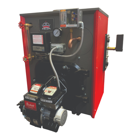
KSB Series
Oil-Fired Steam Boilers
INSTALLATION INSTRUCTIONS
These instructions must be affixed on or adjacent to the boiler
Improper installation, adjustment, alteration, service or maintenance can cause property damage,
injury, or loss of life. For assistance or additional information, consult a qualified installer, service
agency or the fuel supplier. Read these instructions carefully before installing, operating, or
servicing this boiler. Keep boiler and any provided component instructions in legible condition and
posted near boiler for reference by owner and service technician.
Models:
KSB065
•
KSB075
•
KSB100
•
KSB125
•
KSB150
•
KSB175
•
KSB200
•
980280B Rev 0, 11-20
D
E S I G N E D
WARNING
L
T O
E A D
9902339
Crown Boiler Company
P.O. Box 14818
3633 I Street
Philadelphia, PA 19134
www.crownboiler.com
Advertisement
Table of Contents

Related Manuals for Crown Boiler KSB Series


Summary of Contents for Crown Boiler KSB Series
- Page 1 E S I G N E D E A D KSB Series Oil-Fired Steam Boilers INSTALLATION INSTRUCTIONS These instructions must be affixed on or adjacent to the boiler WARNING Improper installation, adjustment, alteration, service or maintenance can cause property damage, injury, or loss of life.
- Page 3 IMPORTANT INFORMATION - READ CAREFULLY All boilers must be installed in accordance with National, State and Local Plumbing, Heating and All boilers must be installed in accordance with National, State and Local Plumbing, Heating and Electrical Codes and the regulations of the serving utilities. These Codes and Regulations may differ Electrical Codes and the regulations of the serving utilities.
- Page 4 DANGER DO NOT store or use gasoline or other flammable vapors or liquids in the vicinity of this or any other appliance. WARNING Improper installation, adjustment, alteration, service or maintenance can cause property damage, personal injury or loss of life. Failure to follow all instructions in the proper order can cause personal injury or death.
- Page 5 WARNINGS FOR THE HOMEOWNER FOLLOW ALL INSTRUCTIONS and warnings printed DO NOT BLOCK AIR FLOW into or around the boiler. in this manual and posted on the boiler. Insufficient air may cause the boiler to produce carbon monoxide or start a fire. INSPECT THE BOILER, BURNER AND CONTROLS ANNUALLY.
- Page 6 WARNINGS FOR THE INSTALLER READ THIS ENTIRE MANUAL before attempting INSTALL ALL GUARDS, cover plates, and installation, start-up, or service. Improper enclosures before operating the boiler. installation, adjustment, alteration, service, or SIZE THE BOILER PROPERLY relative to the design maintenance may cause serious property damage, heat load or, if using domestic hot water priority, personal injury, or death.
-
Page 7: Table Of Contents
Table of Contents Product Description ................6 Specifications ..................6 III. Before Installing ..................7 Field Assembly ..................8 Locating the Boiler ................11 Air for Combustion & Ventilation ............12 VII. Venting ....................17 VIII. System Piping ..................19 Indirect &... -
Page 8: Product Description
I Product Description The KSB series boiler is a cast iron oil-fired low pressure steam boiler designed for use in closed heating systems. This boiler must be vented by natural draft into a lined masonry or metal chimney, or Type L vent. An adequate supply of air for combustion, ventilation and dilution of flue gases must be available in the boiler room. -
Page 9: Before Installing
TABLE 2.2: OPTIONAL TANKLESS HEATER RATINGS MODEL RATING (GPM) KSB065 2.25 KSB075 2.25 KSB100 2.50 KSB125 2.75 KSB150 3.00 KSB175 3.25 KSB200 3.50 Tankless heater ratings based on 40F inlet water, 140F outlet water, and 190F boiler water. Ratings are also based on 5 minute intermittent draws with 10 minutes between draws. -
Page 10: Field Assembly
If a power venter must be used, it is the responsibility of the installer and power venter manufacturer to “engineer” the power vent system. CROWN BOILER CO. WILL ASSUME NO RESPONSIBILITY FOR DAMAGE TO SIDING, ETC. FROM A POWER VENTED OIL-FIRED BOILER. - Page 11 3) Plug the burner cord into the connector located inside the junction box on the front of the boiler. Secure the cover plate that is on the burner cord to the junction box. This plate has keyhole slots that allow it to be mounted/unmounted for servicing without removing the junction box screws.
- Page 12 FIGURE 4.1: FIELD INSTALLATION OF FLUE BAFFLES...
-
Page 13: Locating The Boiler
V Locating the Boiler WARNING Failure to observe the following location requirements could result in property damage, a fire, explosion or carbon monoxide (CO) hazard. 1) Clearances: • Observe the minimum clearances shown below. Except as noted, these clearances apply to all combustible con- struction, as well as noncombustible walls, ceilings and doors. -
Page 14: Air For Combustion & Ventilation
FIGURE 5.1: INSTALLATION OVER A COMBUSTIBLE FLOOR VI Air for Combustion and Ventilation WARNING • Insufficient combustion air supply may result in the production and release of soot or deadly carbon monoxide (CO) into the home which can cause property damage, severe personal injury or death. - Page 15 For Buildings of Other than Unusually Tight Construction 1) Determine whether the boiler is to be installed in a confined space - A confined space is defined as having a volume less than 50 cubic feet per 1000 BTU/hr input of all appliances installed in that space. To determine whether the boiler room is a confined space: Total the input of all appliances in the boiler room in thousands of BTU/hr.
- Page 16 2) Unconfined Space - Natural infiltration into the boiler room will normally provide adequate air for combustion and venti- lation without additional louvers or openings into boiler room. 3) Confined Space - Provide two openings into the boiler room, one near the floor and one near the ceiling. The top edge of the upper opening must be within 12”...
- Page 17 FIGURE 6.2: ALL AIR FROM OUTDOORS, VIA VENTILATED ATTIC FIGURE 6.3: ALL AIR FROM OUTDOORS, USING OPENINGS INTO BOILER ROOM...
- Page 18 FIGURE 6.4: ALL AIR FROM OUTDOORS, USING HORIZONTAL DUCTS INTO BOILER ROOM...
-
Page 19: Venting
VII Venting WARNING • Improper venting may result in property damage and/or the release of flue gases, which contain deadly carbon monoxide (CO), into the home, resulting in severe personal injury or death. • Inspect existing chimney before installing boiler. Failure to clean or replace damaged pipe or tile lining will cause property damage, severe personal injury or death. - Page 20 2) Acceptable Vent Connectors - The following may be used for vent connectors: • Listed Type L vent. • Single Wall Galvanized Pipe - Use 0.018” (26 gauge) or heavier. 3) Chimney and Vent Connector Sizing - See Table 2 for minimum vent connector and chimney sizing. 4) Do not vent this appliance into any portion of a mechanical vent system operating under positive pressure.
-
Page 21: System Piping
VIII System Piping WARNING • Install boiler so that the electrical components are protected from water (dripping, spraying, rain, etc.) During appliance operation and service (circulator replacement, etc.). • Operation of this boiler in a system having significant amounts of dissolved oxygen can cause severe heat exchanger corrosion damage. - Page 22 Avoid the common piping mistakes shown in Figure 8.1. This applies even if the existing boiler has one of the piping mistakes shown in Figure 8.1 and appears to be working. If two or more steam mains must be connected to the boiler, connect a separate take-off for each main into the header between the riser(s) and equalizer.
-
Page 23: Indirect & Tankless Water Heater Piping
All KSB series boilers are equipped with tappings to permit the connection of a Crown Mega-Stor, or other indirect water heater. In this type of system, hot boiler water is drawn from below the water line and passed through the heat exchanger in the indirect water heater. - Page 24 TANKLESS HEATER PIPING DANGER-SCALD HAZARD The control supplied with this boiler is not intended to provide accurate control of the domestic water temperature leaving the tankless heater. An installer supplied, ASSE 1017 or ASSE 1070 certified tempering valve is therefore REQUIRED as part of this boiler’s installation.
-
Page 25: Fuel Line Piping
FIGURE 9.1: TANKLESS HEATER PIPING X Fuel Line Piping WARNING • Under no circumstances can copper with sweat style connectors be used. • Do not use compression fittings. • Oil piping must be absolutely airtight or leaks or loss of prime may result. •... - Page 26 FIGURE 10.1: ONE-PIPE GRAVITY SYSTEM Depending on the location of the fuel oil storage tank in relation to the oil burner, there are four types of oil piping systems generally being used: a) ONE-PIPE GRAVITY SYSTEM - used when a fuel oil storage tank is positioned above an oil burner fuel pump. See Figure 10.1.
- Page 27 7) Attach required piping between burner fuel pump and fuel oil storage tank. Install one fuel shut-off valve near the storage tank and second fuel shut-off valve near the oil burner fuel pump. Use heavy wall copper tubing in a continuous run. On two-pipe systems, the return line should terminate 3”...
-
Page 28: Wiring
FIGURE 10.4: TWO-PIPE LIFT SYSTEM XI Wiring WARNING • All wiring and grounding must be done in accordance with the authority having jurisdiction or, in the absence of such requirements, with the National Electrical Code (ANSI/NFPA 70). • Disconnect electrical power to the boiler and heating system before servicing. Positively assure that no voltage is present. - Page 29 2) 24V Thermostat Wiring - Follow thermostat manufacturer instructions. To insure proper thermostat operation, avoid installation in areas of poor air circulation, hot spots (near any heat source or in direct sunlight), or cold spots (outside walls, walls adjacent to unheated areas, locations subject to drafts). Provide Class II circuit between thermostat and boiler.
- Page 30 FIGURE 11.0: 120V BOILER CONNECTIONS DIAGRAM (See Figs 11.1a-c for burner and low voltage thermostat wiring) Beckett 7505: FIGURE 11.1a: CONNECTIONS DIAGRAM FOR BECKETT BURNER PRIMARY CONTROL...
- Page 31 Carlin 40200: FIGURE 11.1b: CONNECTIONS DIAGRAM FOR CARLIN BURNER PRIMARY CONTROL Riello 530SE: FIGURE 11.1c: CONNECTIONS DIAGRAM FOR RIELLO BURNER PRIMARY CONTROL...
- Page 32 FIGURE 11.2: INDIRECT WATER HEATER FIELD WIRING...
-
Page 33: Start-Up & Checkout
XII Start-up and Checkout Use the following procedure for initial start-up of the boiler: WARNI NG • Never attempt to fill a hot empty boiler. • Make sure that the area around the boiler is clear and free from combustible materials, gasoline, and other flammable vapors and liquids. - Page 34 20) Verify that the smoke level still does not exceed #1 and that the draft over fire is -0.02 inch w.c. 21) Turn off the burner and remove pressure gauge. Install and tighten gauge port plug, than restart the burner. 22) Check for clean cutoff of the burner.
- Page 35 TABLE 12.0a: BECKETT BURNER CONFIGURATION AND SETUP DATA BOILER MODEL KSB065 KSB075 KSB100 KSB125 KSB150 KSB175 KSB200 BURNER MODEL AIR TUBE COMBO. 70MMAQ 70MMAQ 70MMAQ 70MDAQ 70MDAQ 70MLAQ 70MLAQ HEAD TYPE STATIC PLATE 3 3/8 3 3/8 3 3/8 2 3/4 2 3/4 NONE NONE...
-
Page 36: Service & Maintenance
TABLE 12.0c: RIELLO BURNER CONFIGURATION AND SETUP DATA BOILER MODEL KSB065 KSB075 KSB100 KSB125 KSB150 KSB175 KSB200 BURNER MODEL 40F5 40F5 40F5 40F5 40F10 40F10 STANDARD DEL. HAGO NOZZLE 1.25/60B 1.35/45B 1.65/45B 0.60/60A 0.85/60W 1.00/60A PUMP PRESS (psi) TURBULATOR SHUTTER SETTING 2.60 2.85 DRAFT OVER FIRE... - Page 37 a) Temporarily install a 1-1/4” inch or larger full port ball valve in place of the 1-1/2” plug. Temporarily pipe the outlet of this valve to a location where hot water and steam can be safely discharged. b) Make sure that this valve is closed and that the water level is at the normal water line. c) If a king valve is present in the steam main takeoff, close it.
- Page 38 NOTICE • Clean the boiler even if there are no significant soot deposits. Failure to remove all sulfur and ash deposits annually can cause severe corrosion damage. • When cleaning the rear flue passage, be careful not to push the brush too far beyond the bottom of the pins.
- Page 39 Important Product Safety Information Refractory Ceramic Fiber Product Warning: The Parts list designates parts that contain refractory ceramic fibers (RCF). RFC has been classified as a possible human carcinogen. When exposed to temperatures about 1805°F, such as during direct flame contact, RFC changes into crystalline silica, a known carcinogen.
-
Page 40: Troubleshooting
XIV Trouble Shooting A. Combustion 1) Nozzles - The selection of the nozzle supplied with this boiler is the result of extensive testing to obtain the best flame shape and efficient combustion. Other brands of the same spray angle and pattern may be used but may not perform at the expected level of CO and smoke. -
Page 41: Parts
XV Parts QUANTITY PER BOILER OR CROWN P.N. QTY. OR CROWN KEY # DESCRIPTION P.N. HEAT EXCH ASSY. WITH COIL OPENING 1 ea. 2800137 2800137 2800137 2800147 2800147 2800157 2800157 HEAT EXCH ASSY. LESS COIL OPENING 1 ea. 2800139 2800139 2800139 2800149 2800149... - Page 42 QUANTITY PER BOILER OR CROWN P.N. QTY. OR CROWN KEY # DESCRIPTION P.N. REVERSIBLE SIDE JACKET PANEL 2 ea. 270523 270523 270523 270524 270524 270525 270525 HEATER SIDE JACKET PANEL 1 ea. 270533 270533 270533 270534 270534 270535 270535 REAR JACKET PANEL 290220 1 ea.
- Page 44 Manufacturer of Hydronic Heating Products P.O. Box 14818 3633 I. Street Philadelphia, PA 19134 www.crownboiler.com...
Need help?
Do you have a question about the KSB Series and is the answer not in the manual?
Questions and answers
How do you drain the boiler on a frequent basis?
To drain the Crown Boiler Series on a frequent basis:
1. Turn off the burner.
2. Drain water from the boiler until about one inch of water is visible in the gauge glass.
3. Run a hose or temporary piping from the boiler drain valve to a safe discharge location.
4. Drain approximately five gallons of water from the boiler.
This is part of the boiler boil-out process to clean out contaminants.
This answer is automatically generated