Table of Contents
Advertisement
Quick Links
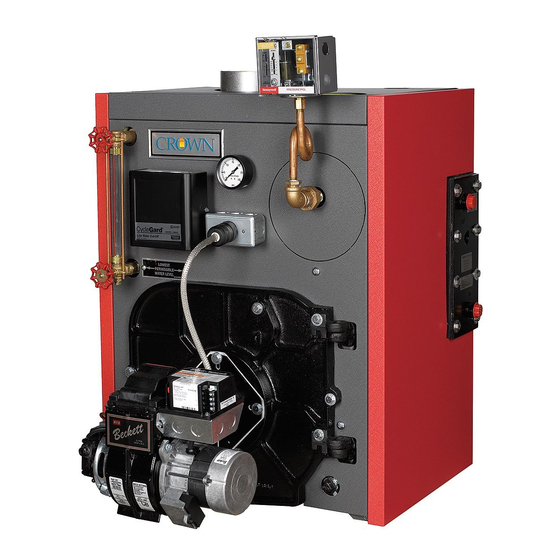
KSZ Series
Oil-Fired Steam Boilers
INSTALLATION INSTRUCTIONS
These instructions must be affixed on or adjacent to the boiler
Improper installation, adjustment, alteration, service or maintenance can cause property damage,
injury, or loss of life. For assistance or additional information, consult a qualified installer, service
agency or the gas supplier. This boiler requires a special venting system. Read these instructions
carefully before installing.
Models:
KSZ065
•
KSZ075
•
KSZ100
•
KSZ090
•
KSZ125
•
KSZ150
•
KSZ120
•
KSZ175
•
KSZ200
•
980280 Rev F, 03-18
D
E S I G N E D
WARNING
L
T O
E A D
Crown Boiler Company
P.O. Box 14818
3633 I Street
Philadelphia, PA 19134
www.crownboiler.com
Advertisement
Table of Contents

Related Manuals for Crown Boiler KSZ Series


Summary of Contents for Crown Boiler KSZ Series
- Page 1 E S I G N E D E A D KSZ Series Oil-Fired Steam Boilers INSTALLATION INSTRUCTIONS These instructions must be affixed on or adjacent to the boiler WARNING Improper installation, adjustment, alteration, service or maintenance can cause property damage, injury, or loss of life.
- Page 3 IMPORTANT INFORMATION - READ CAREFULLY All boilers must be installed in accordance with National, State and Local Plumbing, Heating and Electrical Codes and the regulations of the serving utilities. These Codes and Regulations may differ from this instruction manual. Authorities having jurisdiction should be consulted before installations are made.
- Page 4 DANGER DO NOT store or use gasoline or other flammable vapors or liquids in the vicinity of this or any other appliance. WARNING Improper installation, adjustment, alteration, service or maintenance can cause property damage, personal injury or loss of life. Failure to follow all instructions in the proper order can cause personal injury or death.
- Page 5 WARNINGS FOR THE HOMEOWNER FOLLOW ALL INSTRUCTIONS and warnings printed or other safeguards are in place to prevent such in this manual and posted on the boiler. damage INSPECT THE BOILER, BURNER AND CONTROLS DO NOT BLOCK AIR FLOW into or around the boiler. ANNUALLY.
-
Page 6: Table Of Contents
WARNING This boiler contains very hot water under high pressure. Do not unscrew any pipe fittings nor attempt to disconnect any components of this boiler without positively assuring the water is cool and has no pressure. Always wear protective clothing and equipment when installing, starting up or servicing this boiler to prevent scald injuries. -
Page 7: Product Description
I Product Description The KSZ series boiler is a cast iron oil-fired low pressure steam boiler designed for use in closed heating systems. This boiler must be vented by natural draft into a lined masonry or metal chimney, or Type L vent. An adequate supply of air for combustion, ventilation and dilution of flue gases must be available in the boiler room. -
Page 8: Before Installing
TABLE 1a: GENERAL SPECIFICATIONS KSZ SPACE HEATING RATINGS DIMENSIONS (in.) NUMBER BURNER HEATING NET AHRI RATING, INPUT AFUE % "A" "B" "C" BASIC BOILER CAPACITY STEAM SECTION MODEL (GAL/HR) (MBH) (Sq. ft) (MBH) KSZ065 0.65 85.1 17-3/8 8 5/16 KSZ075 0.75 84.5 17-3/8... -
Page 9: Locating The Boiler
If a power venter must be used, it is the responsibility of the installer and power venter manufacturer to “engineer” the power vent system. CROWN BOILER CO. WILL ASSUME NO RESPONSIBILITY FOR DAMAGE TO SIDING, ETC. FROM A POWER VENTED OIL-FIRED BOILER. - Page 10 • A 24” service clearance is required on the left side of KSZ series boilers equipped with float type low water cut- offs. This is to facilitate low water cut-off maintenance. 2) If listed Type L vent is used, follow vent pipe manufacturer recommendations for minimum clearances.
-
Page 11: Air For Combustion & Ventilation
V Air for Combustion and Ventilation WARNING • Insufficient combustion air supply may result in the production and release of soot or deadly carbon monoxide (CO) into the home which can cause property damage, severe personal injury or death. • This boiler is not designed for use in a space that is depressurized relative to the outdoors. - Page 12 FIGURE 4: BOILER INSTALLED IN CONFINED SPACE, ALL AIR FROM INSIDE 2) Unconfined Space - Natural infiltration into the boiler room will normally provide adequate air for combustion and venti- lation without additional louvers or openings into boiler room. 3) Confined Space - Provide two openings into the boiler room, one near the floor and one near the ceiling. The top edge of the upper opening must be within 12”...
- Page 13 FIGURE 5: ALL AIR FROM OUTDOORS, VENTILATED CRAWL SPACE AND ATTIC FIGURE 6: ALL AIR FROM OUTDOORS, VIA VENTILATED ATTIC...
- Page 14 FIGURE 7: ALL AIR FROM OUTDOORS, USING OPENINGS INTO BOILER ROOM FIGURE 8: ALL AIR FROM OUTDOORS, USING HORIZONTAL DUCTS INTO BOILER ROOM...
-
Page 15: Venting
FIGURE 9: TYPICAL VENT SYSTEM INSTALLATION AND COMPONENTS 1) Acceptable Chimneys - The following chimneys may be used to vent a KSZ series boiler: • Listed Type L vent - Install in accordance with the manufacturer’s instructions, the terms of its listing, and applicable codes. - Page 16 2) Acceptable Vent Connectors - The following may be used for vent connectors: • Listed Type L vent. • Single Wall Galvanized Pipe - Use 0.018” (26 gauge) or heavier. 3) Chimney and Vent Connector Sizing - See Table 2 for minimum vent connector and chimney sizing. The vent connector size must not be smaller than the boiler flue collar diameter.
-
Page 17: System Piping
VII System Piping WARNING • Install boiler so that the electrical components are protected from water (dripping, spraying, rain, etc.) During appliance operation and service (circulator replacement, etc.). • Operation of this boiler in a system having significant amounts of dissolved oxygen can cause severe heat exchanger corrosion damage. - Page 18 Avoid the common piping mistakes shown in Figure 11. This applies even if the existing boiler has one of the piping mistakes shown in Figure 11 and appears to be working. If two or more steam mains must be connected to the boiler, connect a separate take-off for each main into the header between the riser(s) and equalizer.
-
Page 19: Indirect & Tankless Water Heater Piping
INDIRECT WATER HEATER PIPING All KSZ series boilers are equipped with tappings to permit the connection of a Crown Mega-Stor, or other indirect water heater. In this type of system, hot boiler water is drawn from below the water line and passed through the heat exchanger in the indirect water heater. - Page 20 TANKLESS HEATER PIPING KSZ Series boilers equipped with tankless heaters are supplied with a Honeywell L4006A limit control and a 3/4 NPT well. For shipping purposes, these components are shipped unmounted. This control is mounted in the 3/4 tapping in the center of the tankless coil.
- Page 21 5) Globe or Ball Valve (Recommended) - Used to adjust the flow through the entire tankless heater system if needed. 6) Unions (Required) - Tankless heaters may require periodic gasket replacement or other maintenance which requires removal of the heater from the boiler. Install unions anywhere in the tankless heater piping that will facilitate removal of the heater.
-
Page 22: Fuel Line Piping
IX Fuel Line Piping WARNING • Under no circumstances can copper with sweat style connectors be used. • Do not use compression fittings. • Oil piping must be absolutely airtight or leaks or loss of prime may result. • Some jurisdictions require the use of a fusible shutoff valve at the tank and/or the burner. In addition, some jurisdictions require the use of a fusible electrical interlock with the burner circuit. - Page 23 Once the type of system has been selected, observe the following: 1) Fuel line piping must be airtight. Do not use compression type fittings for tubing connections in fuel line piping. Use only listed flare type fittings. Cast iron threaded fittings shall not be used for wrought iron or steel piping connections. 2) Piping shall be substantially supported and protected against physical damage and corrosion where required.
- Page 24 FIGURE 15: TWO-PIPE GRAVITY FEED SYSTEM FIGURE 16: TWO-PIPE LIFT SYSTEM...
-
Page 25: Wiring
X Wiring WARNING All wiring and grounding must be done in accordance with the authority having jurisdic- tion or, in the absence of such authority, with the National Electric Code (ANSI/NFPA 70). 1) 120 Volt Wiring - Provide the boiler with its own 15A branch circuit with fused disconnect. How the 120 volt connec- tions are made depends upon the type of low water cut-off supplied with the boiler. - Page 26 FIGURE 17: INDIRECT WATER HEATER FIELD WIRING Feeder Wiring for Boilers Equipped with Hydrolevel CG450 Low Water Cut-offs 1) Using Hydrolevel VXT-120 feeder - Do not alter factory boiler wiring. Connect VXT-120 to CG450 as follows: • Connect the BLACK lead on the feeder to terminal A on the CG450. •...
- Page 27 FIGURE 18a: WIRING MCDONNELL & MILLER 101A-120 OR HYDROLEVEL VXT-120 FEEDER TO BOILER EQUIPPED WITH #67 L.W.C.O. FIGURE 18b: WIRING MCDONNELL & MILLER WF2-U-120 FEEDER TO BOILER EQUIPPED WITH #67 L.W.C.O.
- Page 28 L4006A LIMIT CONTROL (TANKLESS-EQUIPPED BOILERS ONLY) INTERRUPTED 24 VOLT THERMOSTAT INTERMITTENT BURNER MOTOR LIMIT VALVE CELL NOTE: BURNER WIRING SHOWN IS FOR BECKETT AFG BURNERS. CONSULT BURNER INSTRUCTION MANUAL FOR OTHER BURNERS FIGURE 19: WIRING (MCDONNELL & MILLER #67 LWCO) L4006A LIMIT CONTROL (TANKLESS-EQUIPPED BOILERS ONLY) INTERRUPTED...
-
Page 29: Start-Up & Checkout
XI Start-up and Checkout WARNING • Never attempt to fill a hot empty boiler. • Make sure that the area around the boiler is clear and free from combustible materials, gasoline, and other flammable vapors and liquids. • Safe reliable operation of this boiler requires that the burner be checked and adjusted by a qualified oil serviceman using combustion test instruments. - Page 30 24) Verify primary control operation and safety features according to procedure outlined in the instructions furnished with control. 25) Check pressure limit control operation. Jump thermostat terminals and allow burner to run until boiler pressure exceeds cut-in pressure plus the differential. The burner should shut down. 26) Check low water cut-off operation.
- Page 31 TABLE 3a: BECKETT BURNER CONFIGURATION AND SETUP DATA BOILER MODEL KSZ065 KSZ075 KSZ100 KSZ090 KSZ125 KSZ150 KSZ120 KSZ175 KSZ200 BURNER MODEL AIR TUBE COMBO. 70MMAQ 70MMAQ 70MMAQ 70MMAQ 70MDAQ 70MDAQ 70MLAQ 70MLAQ 70MLAQ HEAD TYPE STATIC PLATE 3 3/8 3 3/8 3 3/8 3 3/8 2 3/4...
-
Page 32: Service & Maintenance
TABLE 3c: RIELLO BURNER CONFIGURATION AND SETUP DATA BOILER MODEL KSZ065 KSZ075 KSZ100 KSZ090 KSZ125 KSZ150 KSZ120 KSZ175 KSZ200 BURNER MODEL 40F5 40F5 40F5 40F10 40F10 40F10 STANDARD DEL. HAGO NOZZLE 0.60/60A 0.85/60W 1.00/60A 1.25/60B 1.35/45B 1.65/45B PUMP PRESS (psi) TURBULATOR SHUTTER SETTING 2.60... - Page 33 4) Clean the boiler flue passages as follows: a) Remove vent connector and piping. b) Remove barometric draft regulator. c) Remove top jacket panel to gain access to boiler flue collector. d) Unscrew four wing nuts and remove canopy retaining carriage bolts, lift off the canopy and ceramic fiber sealing strips.
- Page 34 NOTICE • Clean the boiler even if there are no significant soot deposits. Failure to remove all sulfur and ash deposits annually can cause severe corrosion damage. • When cleaning the rear flue passage, be careful not to push the brush too far beyond the bottom of the pins.
- Page 35 Important Product Safety Information Refractory Ceramic Fiber Product Warning: The Parts list designates parts that contain refractory ceramic fibers (RCF). RFC has been classified as a possible human carcinogen. When exposed to temperatures about 1805°F, such as during direct flame contact, RFC changes into crystalline silica, a known carcinogen.
-
Page 36: Parts
XIII Parts QUANTITY PER BOILER OR CROWN P.N. QTY. OR CROWN KEY # DESCRIPTION P.N. HEAT EXCH ASSY. WITH COIL OPENING 1 ea. 2800137 2800137 2800137 2800147 2800147 2800147 2800157 2800157 2800157 HEAT EXCH ASSY. LESS COIL OPENING 1 ea. 2800139 2800139 2800139... - Page 38 QUANTITY PER BOILER OR CROWN P.N. QTY. OR CROWN KEY # DESCRIPTION P.N. REVERSIBLE SIDE JACKET PANEL 2 ea. 270523 270523 270523 270524 270524 270524 270525 270525 270525 HEATER SIDE JACKET PANEL 1 ea. 270533 270533 270533 270534 270534 270534 270535 270535 270535...
- Page 40 Manufacturer of Hydronic Heating Products P.O. Box 14818 3633 I. Street Philadelphia, PA 19134 www.crownboiler.com...
Need help?
Do you have a question about the KSZ Series and is the answer not in the manual?
Questions and answers