Table of Contents
Advertisement
Quick Links
RuiDa Technology Co., Ltd
Addr:
3th
floor,Technology
Avenue,Nanshan
Province,P.R.China
Tel:
0755--26066687
Fax:
0755--26982287
E-mail:
sales@rd-acs.com
Web:
www.rd-acs.com
SHENZHEN RUIDA TECHNOLOGY
Read this manual before operation
The content include of electric connections and operating steps
Read the manual to operate the systems
Building,NO.,1067
District,Shenzhen
city,Guangdong
RDC5121 Control System Manual
RDC5121
Control System Manual
Nanhai
https://www.ruidacontroller.com
Advertisement
Table of Contents

Related Manuals for RD RDC5121


Summary of Contents for RD RDC5121
- Page 1 RDC5121 Control System Manual Read this manual before operation The content include of electric connections and operating steps Read the manual to operate the systems RDC5121 Control System Manual RuiDa Technology Co., Ltd Addr: floor,Technology Building,NO.,1067 Nanhai Avenue,Nanshan...
- Page 2 RDC5121 Control System Manual COPYRIGHT All rights reserved.You may not reproduce, transmit, store in a retrieval system or adapt thispublication, in any form or by any means, without the prior written permissionof RuiDa, except as allowed under applicable copyright laws. We have identifiedwords that we consider as trademarks.
- Page 3 RDC5121 Control System Manual CERTIFICATION DECLARATION The product has been certified by the CE (Commutate European) safety certification. It has passed the corresponding conformity assessment procedure and the manufacturer's declaration of conformity, in accordance with the relevant EU directive. ROHS This product has been certified by EU legislation (Restriction of Hazardous Substances) Safety certification;...
- Page 4 RDC5121 Control System Manual SAFETY INFORMATION When using this system, please make sure the operation is correct and the usage is safe. Some signs or text will be used to remind you to pay attention to the dangerous matters and some important information.
- Page 5 RDC5121 Control System Manual Sign in、Devanning、Examine cargo The product itself with plastic or metal shell, can protect the external electrical components from damage. The products are packed in foam bags and anti-static bags. If there is any external damage to the package, check the equipment and notify the carrier and carrier in writing of the damage.
-
Page 6: Table Of Contents
RDC5121 Control System Manual Contents Chapter 1 Installation Size........................... 1 1.1 Installation Size of MainBoard’s back..................... 2 1.2 Installation Size of MainBoard’s front.....................3 Chapter 2 Electric connection........................4 2.1 Electric connection..........................5 Chapter 3 Description of Interface Signal for MainBoard................6 3.1 Interface of Main Power Source JP1.................... -
Page 7: Chapter 1 Installation Size
RDC5121 Control System Manual Section 1 Installation Size CONTENTS: Installation Size of MainBoard’s back Installation Size of MainBoard’s front SHENZHEN RUIDA TECHNOLOGY... -
Page 8: Installation Size Of Mainboard's Back
RDC5121 Control System Manual 1.1 Installation Size of MainBoard’s back The unit of all sizes is millimeter (mm) and the size accurate to 0.1mm (the four holes are symmetrical) Figure Recommended opening size: SHENZHEN RUIDA TECHNOLOGY... -
Page 9: Installation Size Of Mainboard's Front
RDC5121 Control System Manual 1.2 Installation Size of MainBoard’s front The unit of all sizes is millimeter (mm) and the size accurate to 0.1mm. Figure SHENZHEN RUIDA TECHNOLOGY... -
Page 10: Chapter 2 Electric Connection
RDC5121 Control System Manual Section 2 Electric connection CONTENTS: Electric connection SHENZHEN RUIDA TECHNOLOGY... -
Page 11: Electric Connection
RDC5121 Control System Manual 2.1 Electric connection Figure 2.1 electric connection connection SHENZHEN RUIDA TECHNOLOGY... -
Page 12: Chapter 3 Description Of Interface Signal For Mainboard
RDC5121 Control System Manual Section3 Description of Interface Signal for MainBoard CONTENTS: Interface of Main Power Source JP1 Udisk Interface PC-USB Interface Special IO port Spacing Input Interface X/Y-Lim X/Y axle Motor Driver Interface X \Y Laser Power Control Interface L-P1... -
Page 13: Interface Of Main Power Source Jp1
RDC5121 Control System Manual 3.1 Interface of Main Power Source JP1 Symbols Definitions +24V 24V power positive (input) 24V power ground (input) 24V power ground (input) This control system employs single 24 power supply. For a certain margin, it is suggested to select 24V/2A power. -
Page 14: Spacing Input Interface X/Y-Lim
RDC5121 Control System Manual machine lies idle, it can be started for work; if the machine is in the working state, the work will be suspended; of the machine is in the suspension, the work will be restarted, that is to say, the function of the pedal switch is the same as that of the “Start/Pause”... -
Page 15: X/Y Axle Motor Driver Interface X \Y
RDC5121 Control System Manual 3.6 X/Y axle Motor Driver Interface X \Y The interfaces of the above four motion axles are the same. The AXIS-X interface is exampled. Symbols Definitions (OC output) Directional signal Pulse signal (OC output) 5V Power positive (output) The polarity of directional signal for driver pulse signal can be set. - Page 16 RDC5121 Control System Manual 2. When the laser is a glass tube the laser power PWM terminal is low level effectiv , this pin will be connected with the laser power PWM end and used to control the power of the laser.
-
Page 17: Chapter 4 Operating Instruction Of Panel
RDC5121 Control System Manual Section 4 Operating Instruction of Panel CONTENTS: Introduction to the Panel and Keys Introduction to the Main Interface FN key SHENZHEN RUIDA TECHNOLOGY... -
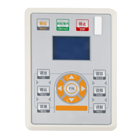
Page 18: Introduction To The Panel And Keys
RDC5121 Control System Manual 4.1 Introduction to the Panel and Keys 4.1.1 The whole panel 4.1.2 Introduction to the Keys :Reset the whole system; :To stop work; :To start or pause the work; SHENZHEN RUIDA TECHNOLOGY... -
Page 19: Introduction To The Main Interface
RDC5121 Control System Manual :Set the relative origin; :To track by the current file’s frame; :Let the Laser to splash; :To stop work, or to exit to some menu; :Validate the change; :The Z/U key can be pressed when the system is idle or the work is ... -
Page 20: Menu Key
RDC5121 Control System Manual Num: To accumulate the work number of the current file MaxPower: To display the max power Spend: To display the speed of work Idle: o display the current status of the machine, such as Idle, Run, Pause, Finish, etc.;... -
Page 21: Max/Min Power Setting
RDC5121 Control System Manual value, then push the “Enter” key to save the change, push the “Esc” key to invalidate the change. 4.2.4 Max/Min power Setting When selecting the "Max power" or "Min power" entry under the menu interface, the following dialog box is displayed: Figure 4.4... -
Page 22: Memory Files
RDC5121 Control System Manual press the "ENTER" key to activate the entry. The "ESC" key returns to the main interface. All the item show as below: Memory files: read the memory file list; Udisk Files: Show U disk file menu;... -
Page 23: Fn Key
RDC5121 Control System Manual Figure 4.8 Copy to memory: copy the target Udisk file to the memory; Delete: delete the selected Udisk file; This system supports such file formats of Udisk as FAT32 and FAT16, but it can identify them when the files are put under the root directory of Udisk. -
Page 24: Manualset
RDC5121 Control System Manual Figure 4.10 Push the “Y+/-“ Keys to move the cursor to one of the entry, then push “Enter” key to restart the selected axis, the screen will show some information when resetting. 4.3.2 ManualSet+ When the cursor is on this item, push the “Enter” key to show as below: Figure 4.11... -
Page 25: Set Fact Para
RDC5121 Control System Manual 4.3.4 Set Fact Para After the “Set Fact Para” is selected and the Enter key pressed, the interface will show the specific password to be entered when set as default parameter. Figure 4.13 Push “X+/-” keys and “Y+/-” keys to select the characters, and push the “Enter” key to valid the characters, when finishing enter the password ,that is to say, the six characters, if the password is error, it prompts there is some error, or, all parameters are stored. - Page 26 RDC5121 Control System Manual Figure 4.14 Push “Y+/-” key to move the green block to the anticipant item, and when the green block is on “enable” items, push “Enter” key to enable or disable the item, when enabled, the small diamonds is green, and when disabled, the small diamonds is grey.
-
Page 27: Language
RDC5121 Control System Manual of origin is 1->2->3->4->1->2……. 4.3.7 Language When the cursor is on this item, push the “Enter” key to show as below: Figure 4.15 Press up and down to select the language type. When you select one of the languages, press “ENTER” to return to the main interface. - Page 28 RDC5121 Control System Manual Thank you for your selection of our production! All the copyright of this manual is owned by Ruida technology. Any person or company can not copy upload and send the manual without Ruida’s permission. Content will be revised or modified. We will not send message to every users.
Need help?
Do you have a question about the RDC5121 and is the answer not in the manual?
Questions and answers