Harman PC 45 Installation & Operating Manual
Corn/pellet stove
Hide thumbs
Also See for PC 45:
- Installation & operating manual (36 pages) ,
- Installation and operating manual (43 pages)
Table of Contents
Advertisement
Installation & Operating Manual
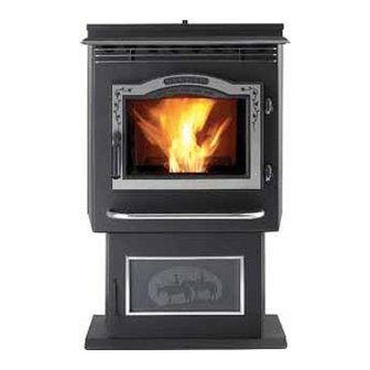
The Harman PC 45 Corn/Pellet Stove
ìCe manuel est disponible en FranÁais sur demandeî
R1
SAFETY NOTICE
PLEASE READ THIS ENTIRE MANUAL BEFORE YOU INSTALL AND USE YOUR NEW ROOM HEATER. FAILURE TO
FOLLOW INSTRUCTIONS MAY RESULT IN PROPERTY DAMAGE, BODILY INJURY, OR EVEN DEATH.
FOR USE IN THE U.S. AND CANADA. SUITABLE FOR INSTALLATION IN MOBILE HOMES
IF THIS HARMAN STOVE IS NOT PROPERLY INSTALLED, A HOUSE FIRE MAY RESULT. FOR YOUR SAFETY, FOLLOW
INSTALLATION DIRECTIONS.
CONTACT LOCAL BUILDING OR FIRE OFFICIALS ABOUT RESTRICTIONS AND INSTALLATION INSPECTION
REQUIREMENTS IN YOUR AREA.
CONTACT YOUR LOCAL AUTHORITY (SUCH AS MUNICIPAL BUILDING DEPARTMENT, FIRE DEPARTMENT, FIRE
PREVENTION BUREAU, ETC.) TO DETERMINE THE NEED FOR A PERMIT.
CETTE GUIDE D'UTILISATION EST DISPONIBLE EN FRANCAIS. CHEZ VOTRE CONCESSIONNAIRE DE HARMAN STOVE
COMPANY.
R1
SAVE THESE INSTRUCTIONS.
Advertisement
Table of Contents

Subscribe to Our Youtube Channel
Related Manuals for Harman PC 45


Summary of Contents for Harman PC 45
- Page 1 Installation & Operating Manual The Harman PC 45 Corn/Pellet Stove ìCe manuel est disponible en FranÁais sur demandeî SAFETY NOTICE PLEASE READ THIS ENTIRE MANUAL BEFORE YOU INSTALL AND USE YOUR NEW ROOM HEATER. FAILURE TO FOLLOW INSTRUCTIONS MAY RESULT IN PROPERTY DAMAGE, BODILY INJURY, OR EVEN DEATH. FOR USE IN THE U.S. AND CANADA. SUITABLE FOR INSTALLATION IN MOBILE HOMES IF THIS HARMAN STOVE IS NOT PROPERLY INSTALLED, A HOUSE FIRE MAY RESULT. FOR YOUR SAFETY, FOLLOW INSTALLATION DIRECTIONS. CONTACT LOCAL BUILDING OR FIRE OFFICIALS ABOUT RESTRICTIONS AND INSTALLATION INSPECTION REQUIREMENTS IN YOUR AREA. CONTACT YOUR LOCAL AUTHORITY (SUCH AS MUNICIPAL BUILDING DEPARTMENT, FIRE DEPARTMENT, FIRE PREVENTION BUREAU, ETC.) TO DETERMINE THE NEED FOR A PERMIT. CETTE GUIDE D'UTILISATION EST DISPONIBLE EN FRANCAIS. CHEZ VOTRE CONCESSIONNAIRE DE HARMAN STOVE COMPANY. SAVE THESE INSTRUCTIONS.
- Page 2 PC 45 Corn/Pellet Stove...
-
Page 3: Table Of Contents
Our exclusive Accordion Heat Exchanger and Air Cooled Combustion Blower allows the PC 45 to produce maximum heat without creating high exhaust temperatures. The Outside Air option can increase heat efficiency even more. The PC 45 can burn corn with moisture levels up to 16%, with 14.5% or less being ideal. It can also burn pellets regardless of ash content. This allows you to buy lower cost fuel and still achieve the same results. Please copy your serial number from the label on your stove to the box below. SERIAL NUMBER Table of Contents SAFETY NOTICE: IF THIS HARMAN STOVE IS NOT PROP- ERLY INSTALLED. A HOUSE FIRE MAY RESULT. FOR Assembly & Installation YOUR SAFETY, FOLLOW THE INSTALLATION DIREC- TIONS CONTACT LOCAL BUILDING OR FIRE OFFICIALS ABOUT RESTRICTIONS AND INSTALLATION INSPECTION Installation 6 REQUIREMENTS IN YOUR AREA. Venting 7 Automatic Operation ESP Control... -
Page 4: Assembly & Installation
Assembly and Installation Unpacking The PC 45 is bolted to the skid to prevent move- ment during shipping. To free the stove from the skid you must re- move the hold-down bolts in the rear of the pedestal base. Installing rear cover panels The rear cover panels are removed from the stove to make it easier to get at the hold-down bolts. The rear cover panels are packed inside the hopper and should be installed on the stove as shown. It is recommended that the rear covers are installed after the unit is in place and the vent pipe is installed. - Page 5 Door Assembly/Installation Tips Bottom Glass Retainer Clip Instructions Follow the instructions in the door kit except for the (2) Glass Retainer Clips bottom glass retainers. Install the special glass supplied with the door kit retainer clips to the bottom of the door. There is a left and right retainer clip with a radius to match the door bottom. The fiber glass rope on the clip must be facing the stove body when installed, NOT FACING THE GLASS!! (4) 10-24 x 3/8" button head allen screws supplied in the door kit These clips are designed to direct the air wash air more evenly. (1) left hand Gasket goes toward the stove Gasket (2) glass retainer clips goes (1) right hand toward Fig. 3 the stove Assembling the door DOOR HINGE ï ...
-
Page 6: Installation
FLOOR PROTECTOR Clothing and other flammable materials should not be placed on or near this unit. Fig. 8 Installation and repair of this Harman Stove should be done by a qualified service person. The appliance Fig. 9: Refer to page 18 for detailed draft settings and should be inspected before use and at least annually by a adjustment procedures. -
Page 7: Venting
Venting Requirements for Terminating the Venting J. The clearance to a non-mechanical air sup- WARNING: Venting terminals must not be re- ply inlet to the building or the combustion air inlet to cessed into a wall or siding. any other appliance must be a minimum of 48î. NOTE: Only PL vent pipe wall pass-throughs K. The clearance to a mechanical air supply and fire stops should be used when venting through inlet must be a minimum of 10 feet. combustible materials. (with outside air installed, 6 feet ) NOTE: Always take into consideration the ef- L. The clearance above a paved sidewalk or a fect the prevailing wind direction or other wind cur- paved driveway located on public property must be rents will cause with flyash and /or smoke when plac- a minimum of 7 feet. ing the termination. M. The clearance under a veranda, porch, deck In addition, the following must be observed: or balcony must be a minimum of 12 inches. A. The clearance above grade must be a mini- NOTE: The clearance to vegetation and other mum of 18". exterior combustibles such as mulch is 36î as mea- B. The clearance to a window or door that may sured from the center of the outlet or cap. This 36î be opened must be a minimum of 48". radius continues to grade or a minimum of 7 feet ( with outside air installed, 18î ) below the outlet. - Page 8 Venting A combustion blower is used to extract the com- bustion gases from the firebox. This causes a nega- tive pressure in the firebox and a positive pressure in the venting system as shown in fig. 10. The longer the vent pipe and more elbows used in the system, the greater the flow resistance. Because of these facts we recommend using as few elbows as pos- sible and 15 feet or less of vent pipe. The maximum horizontal run should not exceed 48". If more than 15 feet of pipe is needed, the diameter should be increased from 3" to 4" because a larger pipe causes less flow resistance. Be sure to use approved pellet vent pipe wall and ceiling pass through fittings to go through combustible walls and ceilings. Be sure to use a starting collar to attach the venting system to the stove. The starting col- lar must be sealed to the stove with high temp...
- Page 9 Venting #1 Preferred method This method provides excellent venting for nor- mal operation and allows the stove to be installed closest to the wall. Two inches from the wall is safe; however, four inches allows better access to remove the rear panel. The vertical portion of the vent should be three to five feet high. This vertical section will provide natural draft in the event of a power failure. 3 ft. Fig. 12 combustibles #2 Preferred method This method also provides excellent venting for normal operation but requires the stove to be installed farther from the wall. The vertical portion of the vent should be three to five feet high and at least three inches from a combustible wall. This vertical sec- tion will provide natural draft in the event of a power failure. If the stove is installed below grade the vent termination should be at least 1 foot above grade.
- Page 10 Venting #3 Installing into an existing chimney ( US only ) This method provides excellent venting for nor- mal operation. This method also provides natural draft in the event of a power failure. If the chimney condition is questionable you may want to install a liner as in method #6. Fig. 14 #4 Installing into an existing fireplace chimney ( US only ) This method provides excellent venting for nor- mal operation. This method also provides natural draft in the event of a power failure. The damper area must be sealed with a steel plate or fiberglass. A cap should be installed on the chimney to keep out rain. If the chimney condition is questionable you may want to install a liner all the way to the top as in method #5. Fig. 15 PC 45 Corn/Pellet Stove...
- Page 11 Venting #5 Installing into an existing fireplace chimney (US and Canada) This method provides excellent venting for nor- mal operation. This method also provides natural draft in the event of a power failure. In Canada and some places in the US it is required that the vent pipe extend all the way to the top of the chimney. In this method a cap should also be installed on the chimney to keep out rain. Be sure to use approved pellet vent pipe fittings. Seal pipe joints with silicone in addition to the sealing system used by the manufacturer. Pipe size should be increased to 4" using this method. Fig. 16 #6 Installing into an existing chimney ( US and Canada ) This method provides excellent venting for nor- mal operation. This method also provides natural draft in the event of a power failure. In Canada and some places in the US it is re- quired that the vent pipe extend all the way to the top of the chimney. The pipe or liner inside the chimney should be 4"diameter. In this method a cap should also be installed on the chimney to keep out rain. Fig. 17 PC 45 Corn/Pellet Stove...
- Page 12 Venting Storm collar Flashing 3" min. 3" min. 3" min. PL vent manufacturer's Minimum flue vent configuration firestop spacer and support No insulation or It is recommended that other combustible outside air be installed with this materials venting configuration. allowed within 3" of the PL vent pipe. (See Page 6 for corner installation clearances) Fig. 18...
-
Page 13: Automatic Operation
AUTOMATIC IGNITION/OPERATION The PC45 corn/pellet stove is more than just automatic ignition, it is also automatic temperature control. The automatic system will allow the fire size to be adjusted to match the heating needs and even put the fire out if necessary. If heat is needed after the fire is out, the PC 45 will automatically re-ignite and adjust the fire size to match the heating need. The totally automatic room sensor mode is recommended because of its efficiency. The unit can be switched between "AUTO" and "MANUAL" at any time during operation. Igniter switch to "AUTO" Room Temperature Mode In "Room Temp Mode" heat output is controlled auto- matically by the Room Sensing Probe. When the Room Sens- ing Probe calls for heat, the stove will increase output. When the Room Sensing Probe is getting close to the set tempera- ture, the stove will begin to level off output and keep the fire burning at just the right temperature to maintain that setting. - Page 14 AUTOMATIC START UP Starting the Fire Igniter Switch to"AUTO"(up position) Make sure the unit is plugged into a 120 VAC, 60 HZ electrical source. The power light should be the only light lit. Anytime there is interruption in power at the receptacle, the combustion blower will run for 1 minute after the power is regained. 1.Turn the Mode Selector to "OFF" Fig. 23 2. Fill the hopper with corn or pellets. 3. Clean the burn pot and housing, if necessary. 4. If starting after an empty hopper, turn the feed adjuster to "TEST" until the fuel is visible in the auger tube opening. This also allows you to check the motors for operation.
- Page 15 MANUAL IGNITION/OPERATION The PC45 Corn/Pellet Stove is capable of manual operation. This also allows the op- erator to manually control operation during an emergency (i.e. ignitor failure, when using a 502H battery backup, or when using certain generators.) The unit can be switched between "AUTO" and "MANUAL" at any time during operation. NOTE: When starting the unit in the "AUTO" mode and switching to "MANUAL", the fire must be large enough to turn the ignitor light off (located on the control board). This is a signal that the start cycle is completed and the fire will not go out. Igniter Switch to "MANUAL" Room Temperature Mode The fire will have to be lit with starting gel and a match, or started automatically, see "Automatic Op- eration". Turn to "Manual" position when the fire is es- tablished. The difference between "AUTO" Room Tempera- ture Mode and "Manual" Room Temperature Mode is that the fire will not go out as the room temperature goes above the control board setting. The unit can only go to low burn and will remain there until it runs out of fuel or until more heat is needed and the feed rate in-...
- Page 16 MANUAL START UP Starting the Fire Igniter Switch to"MANUAL" (down position) Make sure the unit is plugged into a 120 VAC, 60 HZ electrical source. The power light should be the only light lit. Anytime there is interruption in power at the receptacle, the combustion blower will run for 1 minute after the power is regained. Burning Corn 1. Turn the Feed Adjuster to desired feed rate, approximately #2. 2. Turn the Mode Selector to "OFF" and then to the desired mode. This will reset the control and start the combustion Fig. 26 motor. 3. Turn the Temperature Dial to the desired setting. 4. Clean the burnpot and housing, if necessary. 5. Fill the burnpot with corn up to the auger shaft. Then place pellets on top of the corn as high as the shelf area. See corn Corn Burnpot burnpot shown on left. 6. Add starting gel on top of the pellets, stir gel into the pellets and corn for faster lighting. 7. Light the starting gel with a match and close the door. Operation will begin when the fire reaches the proper temperature.
-
Page 17: Esp Control
Allows you to choose between Room Temp Temp Mode using the outer scale marked in degrees Mode, Stove Temp Mode, or OFF. Also allows Fahrenheit. It also allows you to adjust the stove you to vary the distribution blower speed by temperature while in Stove Temp Mode using the inner turning the knob to the high or low side of each scale marked from 1 to 7. mode. Status light error message 6 Blinks : Indicates that the control has calculated 1 Blink: Indicates control board self diagnostic fail- poor or incomplete combustion occurring for more ure. This requires a manual reset*. than 50 minutes. See Troubleshooting section for 3 Blinks: Indicates ESP (Exhaust Sensing Probe) more details. failure. This requires a manual reset*. * Manual reset- Disconnect power cord for a few 4 Blinks: Can occur only in Room Temp Mode and seconds and reconnect. If error still occurs call your indicates Room Sensing Probe failed or not installed. Harman Dealer. If a Room Sensing Probe is then installed, the sta- tus light will automatically reset. NOTE: Unit will not start in "AUTO" with this status error. 5 Blinks (In Igniter Auto. Mode Only): Indicates that the unit has failed to light within the 45 minute start cycle. To reset - Turn Mode Selector to "OFF", then turn to either mode again. PC 45 Corn/Pellet Stove... - Page 18 Low Draft Voltage Adjustment Combustion Motor Speed Control Low draft only set point. The small straight screwdriver slot is plastic; therefore, the unit can be adjusted while in operation. Draft Meter bolt hole location On a PC 45 the draft hole is under the left rear corner of the firebox. Fig.29 Fig. 30 Low Draft Voltage Adjustment These units are pre-tested at the factory with A simple draft test should be performed after exactly 120 Volts A.C., 60 Hz. They are checked and completing the flue pipe installation. To record the adjusted for firebox tightness, gasket leakage, motor results for future reference: operation and ignitor operation. The PC 45 is then 1. Plug unit into a 120VAC, 60 HZ outlet.
-
Page 19: Maintenance
Maintenance Removing Ashes: The frequency in which you will need to empty the ash pan will vary depending on the conditions that the stove has been operating in. For example: A stove burning on high continuously will probably need the ashes removed every 1 to 2 days, whereas a stove burning on low or cycling off periodically may be able to go 3 to 8 days or longer. Ashes should be placed in a metal con- tainer with a tight fitting lid. The closed con- tainer of ashes should be placed on a noncom- bustible floor or on the ground, well away from all combustible materials, pending final disposal. If ashes are disposed of by burial in soil or oth- erwise locally dispersed, they should be re- tained in the closed container until all cinders have thoroughly cooled. It is recommended that the stove is cold and shut down when removing ash pan. - Page 20 Maintenance (Cleaning continued) 5. Remove the ash pan. 6. Remove the combustion blower cover by turning the blower cover latch vertical as shown in fig. 32. Slide the cover out of the slot on the left. This will expose the combustion blower wheel and flue outlet, fig. 35. 7. Clean the blower wheel with a brush and a vacuum cleaner. Fig. 33: Fig. 34 Latch "closed "with 8. Use a brush to clean the flue, being careful not to blower cover in place. Burn pot clean-out is closed. damage the ESP probe. The flue goes straight through into the vent pipe therefore, the vent pipe can also be cleaned to some extent through the flue ESP probe outlet. 9. Reinstall the blower cover and relatch. 10. Slide ash pan into the stove and latch into place. Cleaning of Feeder Fines Area 1. Remove the rear shields to access the feeder Fig. 36: Blower cover Fig. ...
- Page 21 Maintenance - Burn Pot Burn Pot Cleaning and Maintenance 1. Be sure the stove power is turned off. 2. Lift up and remove the front plate lock and front plate. Set aside the front plate. 3. Remove the auger extension by pulling toward you, then set aside (corn burnpot only) 4. Remove burnpot grate and set aside. 5. Clean all fines and debris that has accumulated. 6. Install the spare "clean" burnpot grate making sure the 2 holes line up with the 2 tabs in the burnpot housing. 7. Now install the spare "clean" auger extension into the auger shaft. Make sure there isn't any corn or debris in the shaft opening. This will prevent the auger extension from being fully inserted into the shaft. 8. Align the auger extension through the hole in the spare "clean" front plate and place front plate against the burnpot grate and housing.
-
Page 22: Trouble Shooting
PC 45 Trouble-Shooting FEEDER DOES NOT FEED SMOKE IS VISIBLE COMING OUT OF VENT 1. No fuel in hopper. 1. Air-fuel ratio is too rich. 2. Firebox draft may be too low for low draft pres- A. Feed rate too high. B. Draft too low caused by a gasket leak. sure switch in feeder circuit to operate. Check for 2. Unit is in an ignition cycle. closed doors, loose or missing gasket on doors or hopper lid, faulty pressure switch. LOW HEAT OUTPUT 3. Feed motor will not run until ESP senses 200 F. 1. Feed rate too low Maybe you did not put enough pellets in the burn 2. Temperature setting too low (Stove Temp Mode) pot before lighting the fire. 3. Draft too low because of gasket leak. 4. Something is restricting flow in the hopper or 4. Poor quality or high moisture fuel. causing the slide plate to stick. 5. Feed motor has failed. Helpful Hints PARTIALLY BURNED FUEL 1. Feed rate too high. Cleaning Burn Pot 2. Draft too low. Whenever your stove is not burning, take the 3. Burn pot may need to be cleaned. -
Page 23: Feeder Parts
P61A Feeder Feeder and Specifications Feeder Body Weldment Differential Switch: 3-20-9301 1-10-02681 Pusher Arm MTNG. Nuts(2) 3-30-80252013 Slide Plate Slab Base T-nut:: 3-31-23756186 1-10-08037 Igniter Element: 3-20-02677 Pillow Block Bearing Igniter Mounting Bracket: 2-00-724121 3-31-3614087 3/8 MPT x 1/4" Barb Brass Inlet Fitting: 3-10-724203 Auger ... - Page 24 Door Options Tabs Tabs Fig. 42 Fig. 43 "Sunrise" Gold Trim Gold Door This kit includes a gold trim piece for the ash lip The gold door (fig. 43) is assembled and in- and a gold Sunrise piece for the door. See Fig. 42. stalled the same as the standard door. Refer to page Referring to the diagram, page 5, note how the 5. Be careful not to scratch the glass and be sure to various components of the door system fit together. clean the gold before starting a fire in the stove. Lay the load door face down on a soft surface. To install ash lip trim, simply slide the trim over Clean the glass thoroughly using a nonabra- the ash lip and into the groove on the trim. sive glass cleaner. Install the glass gasket around the outer edge of the front face of the door glass Cleaning Gold carefully to insure proper sealing. Note: There are 4 tabs on the Sunrise. These The gold plated door and gold Sunrise should tabs have a step on the front side and are flush on never be buffed or polished. Abrasive cleansers and the back side. Place the "Sunrise" in the door so the metal polishes will remove the plating and therefore...
-
Page 25: Options
OPTIONS Side Heat Shields Optional Pellet Burnpot Grate Side heat shields are available to reduce the The pellet burnpot grate is required to burn clearance to combustible materials. See Fig. 44. pellet fuel. The corn burnpot and pellet burnpot grates were designed to be interchangeable, and are easily installed and removed without the use of tools. Each PC 45 comes with (2) corn burnpot grates to aid in continual burning of corn in the event that the corn burnpot needs to be cleaned. Please note they are both corn burnpot grates, not one corn grate and one pellet grate. Fig. 44 Hopper Extension The hopper extension allows you to put more Fig. 46: Optional Pellet Burnpot Grate pellet fuel in the hopper and extends burn time on one load of corn. The hopper extension adds 65 pounds to the existing 80 pound hopper capacity, Optional Hopper Screen (Corn Strainer) allowing you to load 145 pounds of corn at one time. -
Page 26: Wiring Diagram
PC 45 Wiring Diagram PC 45 Corn/Pellet Stove... -
Page 27: Parts List
PC 45 Parts List Description Part Number Hopper Gasket(6 ft.) 0-88-00248 Ash Pan Assembly 1-10-05800 Burnpot Housing Weldment 1-10-724103 Burnpot Grate Weldment (corn) 1-10-724108 Burnpot Front Plate Weldment (corn) 1-10-724107 Burnpot Front Plate Lock 2-00-724105 Corn Auger Extension 3-00-02676 Ceramic Insert Plate 2-00-724104 Ceramic Insert 3-20-05238 Wiring: Main Harness 3-20-02680 Neutral Harness 3-20-02681 Air Pump Ground Wire 3-20-02682 Combustion Blower Ground Wire 3-20-02683 Distribution Blower Ground Wire 3-20-00496 Right Rear Shield 2-00-06468-1 Left Rear Shield 2-00-06468-2 Arrow Scraper 2-00-773850 Thermister Probe 3-20-00744 Room Sensor 3-20-00906... -
Page 28: Warranty
HARMAN GOLD WARRANTY (for corn stove) 6 YEAR TRANSFERABLE LIMITED WARRANTY (Residential) 1 YEAR LIMITED WARRANTY (Commercial) Harman Stove Company warrants its products to be free from defects in material or workmanship, in normal use and service, for a period of 6 years from the date of sales invoice and for mechanical and electrical failures, in normal use and service, for a period of 3 years from the date of sales invoice. If defective in material or workmanship, during the warranty period, Harman Stove Company will, at its option, repair or replace the product as described below. The warranty above constitutes the entire warranty with respect to Harman Stove Company products. HARMAN STOVE COMPANY MAKES NO OTHER WARRANTY, EXPRESSED OR IMPLIED, INCLUDING ìANYî WARRANTY OF MERCHANTABILITY, OR WARRANTY OF FITNESS FOR A PARTICULAR PURPOSE. No employee, agent, dealer, or other person is authorized to give any warranty on behalf of Harman Stove Company. This warranty does not apply if the product has been altered in any way after leaving the factory. Harman Stove Company and its agents assume no liability for ìresultant damages of any kindî arising from the use of its products. In addition, the manufacturer and its warranty administrator shall be held free and harmless from liability from damage to property related to the operation, proper or improper, of the equipment. THERE ARE NO WARRANTIES WHICH EXTEND BEYOND THE DESCRIPTION ON THE FACE HEREOF. THESE WARRANTIES APPLY only if the device is installed and operated as recommended in the userís manual. THESE WARRANTIES WILL NOT APPLY if abuse, accident, improper installation, negligence, or use beyond rated capacity causes damage. HOW TO MAKE A CLAIM - Any claim under this warranty should be made to the dealer from whom this appliance was purchased. Then contact is made with manufacturer, giving the model and serial numbers, the date of...
Need help?
Do you have a question about the PC 45 and is the answer not in the manual?
Questions and answers