Table of Contents
Advertisement
Quick Links
Triplex Sales
1-847-839-8442
www.triplexsales.com
I N S T R U CT I O N M A N UA L
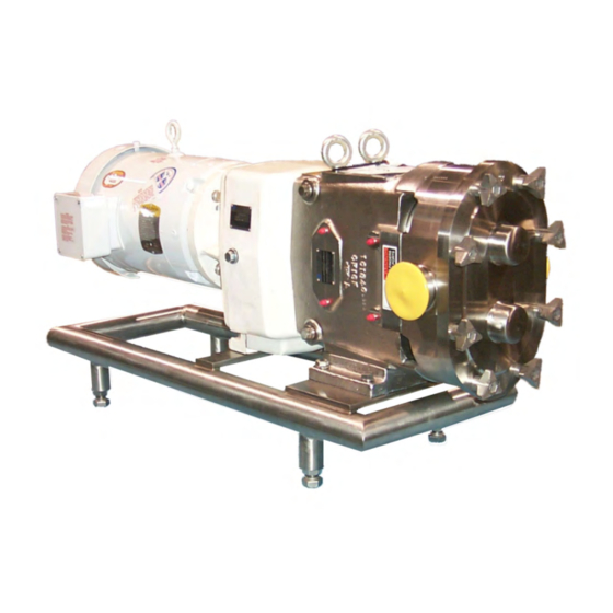
Waukesha ISR
I N T E G R A L S P E E D R E D U C E R S E R I E S
F O R M N O . : 9 5 - 0 3 0 1 0
R E V I S I O N : 0 8 / 1 9 9 7
R E A D A N D U N D E R S TA N D T H I S M A N UA L P R I O R TO O P E R AT I N G O R S E R V I C I N G T H I S P R O D U CT.
FPO
Advertisement
Table of Contents

Related Manuals for SPX Waukesha Cherry-Burrell


Summary of Contents for SPX Waukesha Cherry-Burrell
- Page 1 Triplex Sales 1-847-839-8442 www.triplexsales.com I N S T R U CT I O N M A N UA L Waukesha ISR I N T E G R A L S P E E D R E D U C E R S E R I E S F O R M N O .
- Page 2 Triplex Sales 1-847-839-8442 www.triplexsales.com 95-03010...
-
Page 3: Safety
Triplex Sales 1-847-839-8442 www.triplexsales.com SAFETY Warnings, cautions and notes are contained in this manual. To avoid serious injury and/or possible damage to equipment, pay attention to these messages. LEVELS OF HAZARDS WARNING Hazards or unsafe practices which COULD result in severe personal injury or death and how to avoid it. CAUTION Hazards or unsafe practices which COULD result in minor personal injury or product or property damage. -
Page 4: Warranty
1-847-839-8442 www.triplexsales.com WARRANTY WAUKESHA CHERRY-BURRELL WARRANTY Seller warrants its products to be free from defects in materials and workmanship for a period of one (1) year from the date of shipment. This warranty shall not apply to products which require repair or replacement due to normal wear and tear or to products which are subjected to accident, misuse or improper maintenance. -
Page 5: Table Of Contents
Triplex Sales 1-847-839-8442 www.triplexsales.com LIST OF CONTENTS PARTS LIST Model 49........22-23 SAFETY ............1 Common Parts WARRANTY............. 4 Motor Attachment Parts Ratio Components and Quantities GENERAL INFORMATION....... 4 PARTS LIST Model 79........24-25 Manual Format Common Parts Ordering/Returning Parts Motor Attachment Parts... -
Page 6: Introduction
Triplex Sales 1-847-839-8442 www.triplexsales.com INTRODUCTION WAUKESHA INTEGRAL SPEED REDUCER The Waukesha Integral Speed Reducer is built for extremely durable service. It creates an in-line link between the drive motor and the pump. Three models (sizes) are available: 49, 79 and 239. The cast iron casing houses quality reduction gearing, presenting eight speed reduction ca- pabilities using two standard motor RPM inputs on the 49 and 79 units, 10 speeds on the 239 unit. -
Page 7: Integral Speed Reducer Components
Triplex Sales 1-847-839-8442 www.triplexsales.com INTRODUCTION INTEGRAL SPEED REDUCER COMPONENTS GEAR CASE FASTENERS REAR CASE REAR IDLER BEARING BEARING PINION SHAFT SPACER SEAL O-RING SEAL RETAINER BUSHING REAR OUTPUT SHAFT BEARING SNAP RING OIL DRAIN SUPPORT PLUG CAP SCREW AND JAM NUT FRONT CASE NARROW GEAR FRONT IDLER BEARING... -
Page 8: Specifications
Triplex Sales 1-847-839-8442 www.triplexsales.com SPECIFICATIONS ISR SIZE USE ON WAUKESHA PUMP Model 49 Models 30, 32, 34, 33A, 5040 Model 79 Models 60, 62, 64, 130, 134, 132, 133A, 5050, 5060 Model 239 Models 220, 222,224, 223A, 5070 STANDARD CONSTRUCTION: Housing: Cast Iron Steel Shafts Ball Bearings... -
Page 9: Installation
Triplex Sales 1-847-839-8442 www.triplexsales.com INSTALLATION ISR TO PUMP DIMENSIONS Figure 2 MODEL 60 PUMP SHOWN MOTOR UNIVERSAL UNIVERSAL PUMP SERIES "U" MODEL FRAME PUMP MODEL 145TC 31.75 A 11.71 30 SERIES 15.91 16.85 20.13 .875 184C 35.0 182TCH 35.0 9.33 9 35 9 35 12.13... -
Page 10: Preparing Isr
Triplex Sales 1-847-839-8442 www.triplexsales.com INSTALLATION PREPARING ISR FOR PUMP INSTALLATION An ISR received as a separate unit will be attached to an existing pump. NOTES: 1.There is NO OIL IN ISR! 2. Pump fasteners are supplied in a separate bag. (On previously installed units, see in-service pump preparation on page 11.) 1. -
Page 11: Mounting Front Case To Pump
Triplex Sales 1-847-839-8442 www.triplexsales.com INSTALLATION MOUNTING FRONT CASE T O PUMP PUMP PUMP SILICONE SEALANT FRONT CASE SOCKET HEAD CAP SCREW OUTPUT GEAR PUMP DRIVE SHAFT SPACER OUTPUT SHAFT RETAINING RING Figure 6 key. Apply a film of Micro Plate 140 gear oil (Figure 6) to pump drive shaft. - Page 12 Triplex Sales 1-847-839-8442 www.triplexsales.com INSTALLATION CASE ASSEMBLY ISR ASSEMBLY - REAR CASE TO FRONT CASE Lubricate all shaft surfaces with Micro Plate FRONT CASE 140 gear oil prior to installing. IDLER SHAFTS 1 GEAR 1. Place the front spacer on the long end of the idler shaft.
-
Page 13: Motor Bolt Torque Table
Triplex Sales 1-847-839-8442 www.triplexsales.com INSTALLATION MOTOR TO SPEED REDUCER 5. Using a rotor nut wrench, rotate the pump shaft so that the keyway in the pinion shaft NOTE: See Bushing and Key Selection Chart bushing is facing up. for specific parts for each model. (Page 14) 6. -
Page 14: Maintenance
Triplex Sales 1-847-839-8442 www.triplexsales.com MAINTENANCE MOTOR REPLACEMENT INSPECTION Inspect speed reducer for excessive noise and oil leaks during monthly inspections. Check oil level at fill plug location. (Figure 10) Excessive oil use would require replacement of oil seals, while excessive noise would indicate bearing and/or gear problems. MOTOR REPLACEMENT The motor must be removed to service the speed reducer. -
Page 15: Isr Disassembly
Triplex Sales 1-847-839-8442 www.triplexsales.com MAINTENANCE ISR DISASSEMBLY CASE SCREWS ISR DISASSEMBLY (Figure 12) 1. Remove two 1/2-13 hex-head cap screws and jam nuts from support foot of rear case. NOTE: On Model 239 support foot screws are 1/2-13 x 2 hex-head machine screws. 2. - Page 16 Triplex Sales 1-847-839-8442 www.triplexsales.com MAINTENANCE ISR DISASSEMBLY 6. Remove pinion shaft spacer from rear case PINION SHAFT RETAINING RING pinion shaft bore. (Figure 15) BEARING 7. Press pinion shaft and bearing out of rear case pinion shaft bore. 8. Remove retaining ring from pinion shaft and press shaft out of bearing.
-
Page 17: Front Case
Triplex Sales 1-847-839-8442 www.triplexsales.com MAINTENANCE FRONT CASE TO PUMP DISASSEMBLY 1. Remove retaining ring and spacer from out- CASE SOCKET HEAD put shaft. (Figure 19) CAPSCREWS (6) NOTE: Spacer is not required on Model 49. RETAINING RING SPACER 2. Slide output gear off output shaft and re- move key. - Page 18 Triplex Sales 1-847-839-8442 www.triplexsales.com MAINTENANCE SPEED REDUCER ASSEMBLY MODELS 49, 79, 239 FRONT CASE ASSEMBLY (Figure 21) FRONT IDLER BEARING (2) 1. Press and seat two front idler bearings into front idler bearing bore. OUTPUT SHAFT AND BEARING NOTE To avoid damage to the bearings, press against outer race when installing bearing in case and inner race when installing bearing on shaft.
-
Page 19: Changing Gear Ratio
Triplex Sales 1-847-839-8442 www.triplexsales.com MAINTENANCE SPEED REDUCER ASSEMBLY 7. Install key in output shaft. (Figure 21) 8. Align keyway in output gear with key in OUTPUT GEAR output shaft and slide output gear onto out- put shaft. SPACER 9. Assemble spacer and retaining ring to out- put shaft. -
Page 20: Rear Case
Triplex Sales 1-847-839-8442 www.triplexsales.com MAINTENANCE SPEED REDUCER ASSEMBLY IDLER SHAFT TO FRONT CASE FRONT CASE ASSEMBLY (Figure 27) IDLER SHAFTS Idler shaft to front idler bearing is a light press 1 GEAR fit. Refer to chart for idler shaft configurations. 1. - Page 21 Triplex Sales 1-847-839-8442 www.triplexsales.com MAINTENANCE SPEED REDUCER ASSEMBLY 3. Press pinion bearing onto shaft and install PINION SHAFT external retaining ring. (Figure 29) NOTE To avoid damage to the bearing, press against RETAINING the INNER RACE. RING BEARING Figure 29 4.
- Page 22 Triplex Sales 1-847-839-8442 www.triplexsales.com PARTS LIST 30,33,35 18 10 27,31,34,36 37,38,39 21 26 7 17 4 47,40 42,43,44 Figure 33 95-03010...
- Page 23 Triplex Sales 1-847-839-8442 www.triplexsales.com PARTS LIST MODEL 49 COMMON PARTS ITEM PART NO. DESCRIPTION QTY. 049 005 001 Gear Box, Front ............1 049 005 005 Gear Box, Rear ............. 1 079 007 144 Narrow Gear, 44 Tooth ..........1 079 008 000 Shaft, Pinion ..............
- Page 24 Triplex Sales 1-847-839-8442 PARTS LIST www.triplexsales.com 34,38,40 27 18 29,35,39,41 12 16 25 42,43 22 Figure 34 44, 45 95-03010...
- Page 25 Triplex Sales 1-847-839-8442 www.triplexsales.com PARTS LIST MODEL 079 COMMON PARTS ITEM PART NO. DESCRIPTION QTY. 049 005 Gear Box, Front ............1 079 005 005 Gear Box, Rear ............. 1 079 007 144 Narrow Gear, 44 Tooth ..........1 079 008 000 Shaft, Pinion ..............
- Page 26 Triplex Sales 1-847-839-8442 www.triplexsales.com PARTS LIST 30,32,34,36,38 28 20 31,33,35,37,39 11 27 40, 41, 42 29 8 19 12,25 Figure 35 43, 44, 45 95-03010...
- Page 27 Triplex Sales 1-847-839-8442 www.triplexsales.com PARTS LIST ITEM PART NO. DESCRIPTION 239 005 001 Gear Box, Front ............1 239 005 005 Gear Box, Rear ............. 1 239 007 082 Narrow Gear, 82 Tooth ..........1 239 008 001 Shaft, Pinion ..............1 239 009 000 Shaft, Output ..............
-
Page 28: Speed Reducer Identification
Triplex Sales 1-847-839-8442 www.triplexsales.com SPEED REDUCER IDENTIFICATION The Integral Speed Reducer has one name tag on it. The MODEL designation is displayed and the current gear RATIO of that model. The SERIAL NUMBER represents the single unat- tached unit, unless the unit is attached to a pump. Then, the serial number will be that of the pump. - Page 29 Triplex Sales 1-847-839-8442 www.triplexsales.com 95-03010...
- Page 30 Triplex Sales 1-847-839-8442 www.triplexsales.com 95-03010...
- Page 31 Triplex Sales 1-847-839-8442 www.triplexsales.com...
- Page 32 P: (262) 728-1900 or (800) 252-5200 F: (262) 728-4904 or (800) 252-5012 E: wcb@spx.com SPX reserves the right to incorporate our latest design and material changes without notice or obligation. Design features, materials of construction and dimensional data, as described in this bulletin, are provided for your information only and should not be relied upon unless confirmed in writing.
Need help?
Do you have a question about the Waukesha Cherry-Burrell and is the answer not in the manual?
Questions and answers