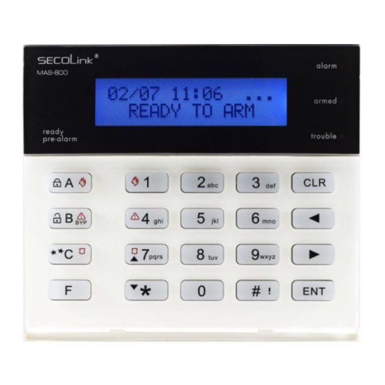
SECOLink KM20B Short Programming Manual - Basic Information
Hide thumbs
Also See for KM20B:
- Short user manual (5 pages) ,
- Short programming manual - basic information (10 pages)
Table of Contents
Advertisement
Quick Links
Intruder alarm system
SAFETY WARNINGS
Short programming manual is recommended for professional installers who are experienced in the installation of intruder alarm
systems and have already read the SECOLINK wiring manual. The wiring manual must be read before the installation to avoid
accidents with high voltage and temperature.
The device must be connected to AC power supply with Protective Earthing. Cable colour and purpose: Phase or Live line (L) - black or
brown cable, Neutral line (N) - blue cable, Protective Earth line (PE) - green cable with a vertical yellow stripe. Only double isolated cables
with cross-sectional area of no less than 0,75 mm shall be used for 230V power supply.
Additional automatic two-pole circuit breaker should be installed in AC electric power circuit in order to prevent over-current and short
circuits. The circuit breaker should be placed close to the system's housing and should be easily reached. Full shutdown could be done by
turning off 230V AC main power supply with automatic two-pole circuit breaker and by disconnecting the battery. Before performing any
installation work or maintenance ALWAYS disconnect the device from the power supply.
DEFAULT TEMPLATE
The system is shipped from the factory with specific default values (further default template) suitable for a typical installation. If the default
template is suitable for your installation, then programming can be simplified. If template is not suitable for your instalation, then you can
easily customize this default template with the software MASCAD. Download MASCAD at www.secolink.eu prior to installation:
1.Connect the keypad to your computer using a USB cable (keypad should not be connected to
system data bus).
2. Download default template from the keypad to software MASCAD (use the tab Project data
sending/receiving).
Note: the default template can be different for different countries. Check a sticker on the keypad for a
country prefix or pre-installed template code. Example: KM20B_EN.
3.Once you customize the predefined template, you can use it to program an individual system or
thousands of systems.
4. DO NOT FORGET to upload the customized template (further project) back to the keypad (use
the tab Project data sending/receiving).
STARTING THE SYSTEM WITH A SINGLE KEYPAD
Upon power-up of the system, the keypad will display a phrase First Start Press [ENT]. It means that the keypad is ready to run an
automatic module registration procedure and later send the default template (or customized project) to the control panel and all
successfully registered system modules.
On the keypad's LCD :
First Start
Press [ENT]
Press the [ENT] key.
STARTING THE SYSTEM WITH MULTIPLE KEYPADS
No Control Address 00 phrase will display upon power-up of the system with multiple keypads. It means that the keypad has the same
address in the system as the other keypads or modules. Press the [Ü] key on a keypad which will become the primary keypad. The primary
keypad should become the one which has a customized project OR it could be any keypad if the default template is not customized. When
the [Ü] key is pressed the keypad will emit a short audible signal and a phrase First Start Press [ENT] will appear on the screen.
Simply press [ENT] if the primary keypad contains a customized project with precise module addressing. If the primary keypad contains
just a default template, then use keys [1], [2], [3], [4], [5] to manually assign the address to each keypad. When all addresses of the keypads
are assigned, return to the primary keypad and press the [ENT] key. All keypads will be registered according to their addresses, which were
given manually. Note: the keypad will remain
unregistered if you will forget to assign the address.
For a small system with a few keypads, it is
recommended to choose addresses of keypads in
01 - 04 range, and for a large system in 01 - 04 and 10
- 15 ranges. This is done ir order to not disturb the
default addresses of other modules with the
addresses of the keypads.
DEFAULT ADDRESSES OF THE MODULES
System manufacturer has provided the modules with default addresses assigned to them. This is done in order to simplify the process of
registration for most frequently used combinations of the system modules (such as PAS808M, KM20B, GSV6U or PAS816, KM24A,
EXM800, EXT116S, GSV6U). While registering modules of a different type, you will not need to enter serial numbers of each module, as
the system will automatically assign default addresses for the modules that are listed below:
For all control panels
For the keypad KM20B, KM24, KM25
For the keypad with a temperature sensor KM24A, KM24G
For extra power supply module PWR20
2
Entering Service
Registering...
Entering Service.
Registration of modules is
Selecting the primary keypad :
No Control
Address 00
Manually assigning addresses to other keypads:
No Control
Address 00
From KM20 to CP
Processing...
Template is being sent
in progress.
Processing...
Press the [Ü] key.
No Control
Address 02
Enter the address
Assigned address 02.
- address 00;
- address 01 or 03;
- address 02 or 04;
- address 04 or none;
System with KM20B keypads
Short programming manual - basic information
KM20Bx
USB cable
Fig. 1 USB connection
Leaving Service
Leaving Service.
to the system.
First Start
Press [ENT]
Processing ...
Primary keypad
No Control
Address 03 Used
Used. Choose another.
MASC
Computer
USB
Page 1
Advertisement
Table of Contents

Related Manuals for SECOLink KM20B


Summary of Contents for SECOLink KM20B
- Page 1 Short programming manual is recommended for professional installers who are experienced in the installation of intruder alarm systems and have already read the SECOLINK wiring manual. The wiring manual must be read before the installation to avoid accidents with high voltage and temperature.
-
Page 2: Entering Service Mode
System with KM20B keypads Intruder alarm system Short programming manual - basic information For the zone/PGM expansion module EXM800 - address 05; For the remote control module EXT016, EXT116S, EXT216 - address 06; For the proximity reader PROX8 - address 06;... - Page 3 PGM outputs. Registered module type is shown on LCD. Available module types: PAS808M, PAS816, PAS832, P16, P32, Type KM20B, KM24, KM24A, KM24G, KM25, EXT016, EXT116S, EXT116VM, EXT216, GSV6U, GSVU, EXM800, PAS832 PROX8, PWR20, and LAN800.
-
Page 4: Zone Programming
System with KM20B keypads Intruder alarm system Short programming manual - basic information The meaning of LED indication depends on module operation mode: Operation mode Small System (up to 3 partitions) - this operation mode is useful when the system has 1 or 2 partitions Small System enabled. - Page 5 2,5 seconds - 25h supervision window; Note: it is recommended to set the supervision time to a minimum of 2 hours if SECOLINK detectors are in use. By default, the system is set to make a zone shutdown when 3 or 7 (use MASCAD to change this number) Z01 Attributes violations of zone are detected.
-
Page 6: Pgm Programming
System with KM20B keypads Intruder alarm system Short programming manual - basic information PGM PROGRAMMING The control panel has three built-in programmable trigger outputs (+BELL, -PGM, +PGM). The system with PAS808M allows up to 8 programmable outputs and bigger systems up to 16 . -
Page 7: Serial Interface Settings
System with KM20B keypads Intruder alarm system Short programming manual - basic information If selected, the output signal is inverted. This is useful when using self-activating alarm sirens. Attributes +InversionOfS If selected, the alarm siren will ding five times when the arming has failed (for example: perimeter zone was Attributes violated or trouble appeared during exit delay). -
Page 8: Gprs Settings
System with KM20B keypads Intruder alarm system Short programming manual - basic information GPRS SETTINGS The GPRS settings menu contains parameters that enable the connection to network. Use MASCAD to program the other settings. Service Mode }Report settings }GPRS settings APN is the name of a gateway between a GPRS mobile network and another computer network, frequently the public Internet. -
Page 9: User Programming
System with KM20B keypads Intruder alarm system Short programming manual - basic information Implemented on detection of smoke or fire for verification. When smoke or fire zone is violated, the system will FZoneVerifTime reset these detectors, then wait for detectors to settle. If a subsequent detection occurs in the same zone within seconds the time that is programmed in Fire Verification Time, the system will emit a fire alarm. - Page 10 If entered the keypad initiates a communications session with the PC. Software MASCAD is used to program Project Loading: SECOLINK intruder alarm system. Note: it is necessary to register modules to the system, if a new module was Open USB Port added to the project by using MASCAD software.
-
Page 11: Service Mode Menu Tree
System with KM20B keypads Intruder alarm system Short programming manual - basic information SERVICE MODE MENU TREE Service Mode System Setup Modules Partitions Zones PGM Outputs Time Settings Security Settings Name Name Name Exit delay (PAS808M) PIN resetting Settings In Use...
Need help?
Do you have a question about the KM20B and is the answer not in the manual?
Questions and answers