Do you have a question about the Wallbox eMH2 and is the answer not in the manual?
Questions and answers
Александр
April 23, 2025
Здравствуйте. Пол года станция работала безупречно , потом стала проблема с сопряжением , машина не видит эту станцию. Всем может быть проблема и что делать? Спасибо.
1 comments:
Mr. Anderson
May 11, 2025
Possible issues with the ABL Wallbox eMH2 not pairing with the vehicle after six months of flawless operation include:
1. The charging cable is not properly plugged in. - Solution: Remove and reinsert the charging connector into the vehicle and the wallbox.
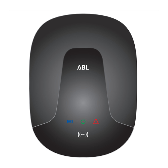
2. The wallbox has detected an error limiting the charging current. - Indication: Red LED flashes once every 10 seconds, blue LED is continuously ON. - Solution: Reinsert charging connector; if issue persists, contact a qualified specialist.
3. Firmware detected a disallowed operating state during a self-test (Error F2). - Indication: Red LED flashes once, green flashes three times, blue flashes once per cycle. - Solution: Switch RCCB off and on; if issue persists, contact a specialist.
4. Internal DC fault current module detected a fault (Error F3). - Indication: Red LED flashes once, green and blue LEDs flash alternately twice. - Solution: Contact a qualified specialist.
5. The wallbox is not powered. - Indication: LEDs are not functioning. - Solution: Check RCCB and switch power off and back on.
If none of these resolve the issue, a qualified specialist electrical contractor should be contacted.


Need help?
Do you have a question about the Wallbox eMH2 and is the answer not in the manual?
Questions and answers
Здравствуйте. Пол года станция работала безупречно , потом стала проблема с сопряжением , машина не видит эту станцию. Всем может быть проблема и что делать? Спасибо.
Possible issues with the ABL Wallbox eMH2 not pairing with the vehicle after six months of flawless operation include:
1. The charging cable is not properly plugged in.
- Solution: Remove and reinsert the charging connector into the vehicle and the wallbox.
2. The wallbox has detected an error limiting the charging current.
- Indication: Red LED flashes once every 10 seconds, blue LED is continuously ON.
- Solution: Reinsert charging connector; if issue persists, contact a qualified specialist.
3. Firmware detected a disallowed operating state during a self-test (Error F2).
- Indication: Red LED flashes once, green flashes three times, blue flashes once per cycle.
- Solution: Switch RCCB off and on; if issue persists, contact a specialist.
4. Internal DC fault current module detected a fault (Error F3).
- Indication: Red LED flashes once, green and blue LEDs flash alternately twice.
- Solution: Contact a qualified specialist.
5. The wallbox is not powered.
- Indication: LEDs are not functioning.
- Solution: Check RCCB and switch power off and back on.
If none of these resolve the issue, a qualified specialist electrical contractor should be contacted.
This answer is automatically generated