Table of Contents
Advertisement
®
Advanced Test Equipment Rentals
www.atecorp.com 800-404-ATEC (2832)
Instruction Manual
P6015A
1000X High Voltage Probe
070-8223-04
Warning
The servicing instructions are for use by qualified
personnel only. To avoid personal injury, do not
perform any servicing unless you are qualified to
do so. Refer to all safety summaries prior to
performing service.
www.tektronix.com
Advertisement
Table of Contents

Related Manuals for Tektronix P6015A


Summary of Contents for Tektronix P6015A
-
Page 1: Instruction Manual
® Advanced Test Equipment Rentals www.atecorp.com 800-404-ATEC (2832) Instruction Manual P6015A 1000X High Voltage Probe 070-8223-04 Warning The servicing instructions are for use by qualified personnel only. To avoid personal injury, do not perform any servicing unless you are qualified to do so. - Page 2 Copyright © Tektronix, Inc. All rights reserved. Tektronix products are covered by U.S. and foreign patents, issued and pending. Information in this publication supercedes that in all previously published material. Specifications and price change privileges reserved. Tektronix, Inc., P.O. Box 500, Beaverton, OR 97077...
- Page 3 Tektronix, with shipping charges prepaid. Tektronix shall pay for the return of the product to Customer if the shipment is to a location within the country in which the Tektronix service center is located. Customer shall be responsible for paying all shipping charges, duties, taxes, and any other charges for products returned to any other locations.
- Page 5 ......1–23 Typical and Nominal Characteristics ..... 1–27 P6015A Instruction Manual...
- Page 6 ......2–17 Using the Replaceable Parts List ......2–18 Index P6015A Instruction Manual...
- Page 7 Table of Contents List of Figures Figure 1–1: The P6015A High-Voltage Probe ... . 1–2 Figure 1–2: Compensation Box with Readout Option ..1–3 Figure 1–3: Assembling the P6015A .
- Page 8 ........2–4 P6015A Instruction Manual...
-
Page 9: General Safety Summary
Do Not Operate With Suspected Failures. If you suspect there is damage to this product, have it inspected by qualified service personnel. Do Not Operate in Wet/Damp Conditions. Do Not Operate in an Explosive Atmosphere. Keep Product Surfaces Clean and Dry. P6015A Instruction Manual... - Page 10 These terms may appear on the product: DANGER indicates an injury hazard immediately accessible as you read the marking. Symbols on the Product. These symbols may appear on the product: Protective Ground CAUTION WARNING Refer to Manual High Voltage (Earth) Terminal P6015A Instruction Manual...
-
Page 11: Service Safety Summary
Use Care When Servicing with Power On. Dangerous voltages or currents may exist in this product. Disconnect power, remove battery (if applicable), and disconnect test leads before removing protective panels, soldering, or replacing components. To avoid electric shock, do not touch exposed connections. P6015A Instruction Manual... - Page 12 Service Safety Summary P6015A Instruction Manual viii...
- Page 13 1-800-833-9200 6:00 a.m. – 5:00 p.m. Pacific time Or contact us by e-mail: tm_app_supp@tek.com For product support outside of North America, contact your local Tektronix distributor or sales office. Service Tektronix offers a range of services, including support Extended Warranty Repair and Calibration services.
- Page 14 Service Safety Summary P6015A Instruction Manual...
- Page 15 User Information...
-
Page 17: Overview
Overview The P6015A is a 100 MW, 3.0 pF high voltage probe with 1000X attenuation. It adds high-voltage measurement capability to oscilloscopes and other measurement devices having an input resistance of 1 MW and an input capacitance of 7 pF to 49 pF. -
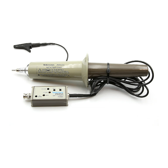
Page 18: Figure 1–1: The P6015A High-Voltage Probe
Overview Guard Ring Figure 1–1: The P6015A High-Voltage Probe 1–2 P6015A Instruction Manual... -
Page 19: Readout Option
BNC connector (Figure 1–2). Some models of Tektronix oscilloscopes (11000 Series and Digital Storage Oscilloscopes) read the code presented by this pin and automatically scale the P6015A measurements by a factor of 1000 to compensate for attenuation. 1000X Readout Pin Figure 1–2: Compensation Box with Readout Option... -
Page 20: Standard Accessories
H banana-plug probe tip H carrying case H instruction manual Options The standard P6015A has a 10-ft cable without 1000X readout. The following options are available: H Option 1R: 10-ft cable and 1000X readout H Option 25: 25-ft cable, no readout H Option 2R: 25-ft cable and 1000X readout 1–4... -
Page 21: Setup
Setup This section tells you how to assemble the P6015A modules as you unpack them from the carrying case. Refer to Figure 1–3 while following these steps: Handle Ground Lead Inner Body Outer Body Figure 1–3: Assembling the P6015A P6015A Instruction Manual... - Page 22 3. Screw the handle into the outer body. 4. Plug the crocodile ground clip onto the ground lead if it is not already attached. 5. Read In Detail, beginning on page 1–7, before attempting to make probe measurements. 1–6 P6015A Instruction Manual...
-
Page 23: In Detail
Handheld Operation The P6015A probe is designed for handheld use when used with the straight or hook shaped probe tips. When using the straight tip, the probe should be held by the plastic handle, behind the probe guard ring, and the tip should be held against the high voltage test point. - Page 24 Readout If your P6015A has the readout option and is being used with an instrument having readout capability, the display automatically corrects for the probe attenuation factor. (Refer to Overview on page 1–1 for information about the P6015A readout option.)
- Page 25 In Detail NOTE. Some oscilloscopes may misinterpret the 1000X attenuation code. Contact your local Tektronix representative if you have questions. Probe Placement CAUTION. Probe placement can be critical in some applications. To minimize Device-Under-Test circuit loading, the P6015A input resistance is very large and input capacitance is very small. Small changes in capacitance near the input resistor will affect the accuracy of the measurement.
-
Page 26: Maximum Input Voltage
In Detail Maximum Input Voltage Table 1–1 and the following paragraphs indicate conditions where the maximum input of the P6015A is reduced. 1,2,3 Table 1–1: Maximum Input Voltage ≥30 Minutes ≥15 Minutes Max. On Time <30 Minutes <15 Minutes Temperature... - Page 27 NOTE. This probe is designed to take voltage measurements between 1.5 kV and 20 kV (DC + peak AC) and impulses up to 40 kV peak. For taking voltage measurements below 1.5 kV, Tektronix makes a variety of probes specifically for these applications.
- Page 28 20 kV Maximum Displayed 10 kV Voltage–10 Foot Cable Maximum Input Voltage @ 5 kV >30 Minutes Duration Maximum Input Voltage Maximum Displayed Voltage–25 Foot Cable 2 kV 1.5 kV Maximum Input Voltage >1.5 kV 1 kV 0.01 1 kHz 10 kHz 100 kMz 1 MHz...
-
Page 29: Probe Grounding
CAUTION. The ground lead is rated at 1 kV maximum. Make sure the ground lead does not contact the probe tip or a high-voltage point on the circuit under test. P6015A Instruction Manual 1–13... - Page 30 If there is any voltage differential, then the point that the tip is connected to is not a valid ground point. (Due to the 1000X attenuation of the P6015A, you may have to increase the sensitivity of the oscilloscope in order to see small voltage differentials.) Perform this check before you attach...
-
Page 31: Probe Compensation
If equipment is substituted, control settings or test equipment setup may need to be altered. Any needed maintenance should be performed before proceeding with compensation. Troubles that become apparent during compensation should be corrected immediately. P6015A Instruction Manual 1–15... -
Page 32: Table 1–2: Test Equipment Required For Short-Form Adjustment
However, because of the 1000X probe attenuation, the system will not display sufficient deflection for optimum adjustment of transient response unless a calibration generator having higher amplitude output is substituted. Requires TM 500 or TM 5000 Series Power Module or equivalent. 1–16 P6015A Instruction Manual... - Page 33 GR center conductor or exposed portions of the probe tip while the generator is on. 3. Insert the tip of the P6015A into the GR center conductor. 4. Set the calibration generator to standard amplitude output of 50 Volts. This setting on a PG 506A produces a 1 kHz square wave.
-
Page 34: Figure 1–6: Zones Affected By Compensation Adjustments
5. Adjust MID 1 (C1) to flatten the area 200 ms from the leading corner. Refer to Figure 1–6 to determine the zones affected by this and the following adjustments. 200 ms Mid 1 100 ms Mid 2 50 ms Mid 3 Figure 1–6: Zones Affected by Compensation Adjustments 1–18 P6015A Instruction Manual... - Page 35 4. Set the calibration generator period to 1 ms, and set the pulse amplitude to display five divisions. 5. Center the waveform on the screen. 6. Adjust HF COMP (R6) for overall flatness of the front corner. P6015A Instruction Manual 1–19...
-
Page 36: Caring For The Probe
H When you are not using the probe, place the probe and its accessories in the case provided. H Don’t use the probe to scrape through insulation, pry compo- nents, or to move components. H When necessary, clean the probe with a damp cloth. 1–20 P6015A Instruction Manual... -
Page 37: Other Considerations
H Because of probe characteristics, small differences in input capacitance between oscilloscopes and scope channels can affect the voltage measurement. The probe compensation should be checked each time the probe is connected to a different input channel or to a different oscilloscope. P6015A Instruction Manual 1–21... - Page 38 In Detail 1–22 P6015A Instruction Manual...
-
Page 39: Specifications
Specifications Warranted Characteristics This section lists the various warranted characteristics that describe the P6015A High Voltage Probe. Included are warranted electrical and environmental characteristics. Warranted characteristics are described in terms of quantifiable performance limits which are warranted. The electrical characteristics listed in Table 1–3 apply under the... -
Page 40: Table 1–3: Warranted Electrical Characteristics
10-ft cable ≤14 ns (calculated from bandwidth) 25-ft cable 1000:1 ±3% (Excluding DC attenuation Test conditions: Oscillo- oscilloscope error) scope input resistance must be 1 MW ±2% Characteristic not checked in manual (ns) = .35/BW (MHz) 1–24 P6015A Instruction Manual... -
Page 41: Table 1–4: Warranted Environmental Characteristics
Less than 70% of Rated No time limit Input Voltage at 0–35_C Greater than 70% of 30 minutes maximum Rated Input Voltage at in any 2.5 hour period 0–35_C 35–50_C 15 minutes maximum in any 2.5 hour period P6015A Instruction Manual 1–25... -
Page 42: Figure 1–7: Humidity Derating Chart
100 M 0° –10° 10 M –20° –30° –40° –50° 100 k –60° –70° 10 k –80° –90° 10 k 100 k 1 M 10 M 100 M Frequency Figure 1–8: Typical Input Impedance and Phase 1–26 P6015A Instruction Manual... -
Page 43: Typical And Nominal Characteristics
Specifications Typical and Nominal Characteristics This section lists the various typical and nominal characteristics that describe the P6015A High Voltage Probe. Nominal characteristics are determined by design and/or inspection. Nominal characteristics do not have tolerance limits. Typical characteristics are described in terms of typical or average performance. -
Page 44: Table 1–6: Nominal Mechanical Characteristics
2.5 × 4.1 × 8.3 cm (1 × 1.6 × 3.25 in) Compensation box Net weight (probe assembly) 10-ft cable 0.66 kg (1.47 lbs) 25-ft cable 0.75 kg (1.66 lbs) Shipping weight (including accessories) 10-ft cable 2.85 kg (6.27 lbs) 25-ft cable 2.93 kg (6.46 lbs) 1–28 P6015A Instruction Manual... - Page 45 WARNING The following servicing instructions are for use only by qualified personnel. To avoid injury, do not perform any servicing other than that stated in the operating instructions unless you are qualified to do so. Refer to all safety summaries before performing any service.
- Page 47 Service Information...
-
Page 49: Performance Verification
Performance Verification The performance verification procedure verifies that the P6015A performs as described in the Specifications section of Chapter 1. This procedure can also be used as an acceptance check. The procedure is given in the next section, Adjustments. The performance verification consists of the long-form compensa-... - Page 50 Performance Verification 2–2 P6015A Instruction Manual...
-
Page 51: Test Equipment Required
Adjustments Recalibration ordinarily is necessary only if the P6015A is being used on a different oscilloscope input or at a drastically different temperature than that at which it was calibrated (a difference greater than ±15_C). The adjustments necessary for recalibration under these conditions are accessible through holes in the top cover of the compensation box. -
Page 52: Table 2–1: Test Equipment Required For Long-Form Adjustment
Requires TM 500 or TM 5000 Series Power Module or equivalent. 2–4 P6015A Instruction Manual... -
Page 53: Long-Form Procedure
This ensures that the adjustment holes are properly aligned with the circuit board. Figure 2–1: Access to Long-Form Adjustments P6015A Instruction Manual 2–5... - Page 54 GR center conductor or exposed portions of the probe tip while the generator is on. 3. Insert the P6015A tip into the GR center conductor. 4. Set the calibration generator to standard amplitude output of 50 Volts. This setting on a PG 506A produces a 1 kHz square wave.
-
Page 55: Figure 2–2: Adjustment Locations
4. The leading corner of the square wave should be level with the trailing corner. If necessary, adjust C5. 5. The top of the waveform should be flat to within ±5% (±1.25 mi- nor divisions). If necessary, perform steps 6 through 8. P6015A Instruction Manual 2–7... -
Page 56: Figure 2–3: Periods Affected By Compensation Adjustments
8. Adjust R5 and C4 to flatten the area 50 ms from the leading corner. Adjustments R2, R4, R5, C1, C2, C4, and C5 interact. Steps 4 and 6 through 8 may have to be repeated several times to achieve optimum flatness. 2–8 P6015A Instruction Manual... - Page 57 7. Adjust R6 for overall flatness of the front corner. 8. Adjust R7 and C7 for a sharp front corner without overshoot. There is interaction between R6, R7, and C7. You may have to repeat steps 7 and 8 to obtain optimum response. P6015A Instruction Manual 2–9...
- Page 58 5. The amplitude of the waveform should be at least 3.5 divisions (0.707 of the amplitude in Step 3). This procedure does not check rise time directly, but it can be approximated by the ratio t = 0.35 / bandwidth. 2–10 P6015A Instruction Manual...
-
Page 59: Preventive Maintenance
CAUTION. Use a mild detergent and damp cloth to clean the probe body. Avoid using chemical cleaning agents that might damage the materials used for the probe body, cable, and compensation box. Before using any other type of cleaner, consult your Tektronix service center or representative. P6015A Instruction Manual... -
Page 60: Troubleshooting And Repair
Troubleshooting and Repair There are two repair options you should consider: H Tektronix Repair — You can ship your P6015A probe to us for repair. H Customer Repair — You can choose to repair the probe yourself. -
Page 61: Mechanical Disassembly And Assembly
CAUTION. Do not attempt to disassemble the inner body assembly. There are no user serviceable components in the inner body assembly, and attempting to open the inner body assembly may result in damage to its internal structure. P6015A Instruction Manual 2–13... -
Page 62: Figure 2–4: Removal And Replacement Of Probe Head
Maintenance Handle Shield Sleeve Cushion Ring Inner Body Outer Body Figure 2–4: Removal and Replacement of Probe Head 2–14 P6015A Instruction Manual... - Page 63 2. Connect the cable to the probe head BNC. 3. Screw the handle in place. 4. Replace the tip. P6015A Instruction Manual 2–15...
- Page 64 3. Replace the top half of the compensation box. Note that the edges are asymetrical (as shown previously in Figure 2–1) and that the top will seat securely only when it is correctly oriented. This ensures that the adjustment holes are properly aligned with the circuit board. 2–16 P6015A Instruction Manual...
-
Page 65: Replaceable Parts
Replaceable Parts This section contains a list of the components that are replaceable for the P6015A. As described below, use this list to identify and order replacement parts. Parts Ordering Information Replacement parts are available from or through your local Tektronix, Inc. -
Page 66: Using The Replaceable Parts List
(:). Because of space limitations, an Item Name may sometimes appear as incomplete. For further Item Name identification, U.S. Federal Cataloging Handbook H6-1 can be used where possible. Abbreviations Abbreviations conform to American National Standards Institute (ANSI) standard Y1.1 2–18 P6015A Instruction Manual... - Page 67 SPECIALTY CONNECTOR CO INC 2100 EARLYWOOD DR FRANKLIN IN 46131 PO BOX 547 74970 JOHNSON E F CO 299 10TH AVE S W WASECA MN 56093–2539 80009 TEKTRONIX INC 14150 SW KARL BRAUN DR BEAVERTON OR 97077–0001 PO BOX 500...
- Page 68 Replaceable Parts 2–20 P6015A Instruction Manual...
- Page 69 131–0602–00 CONN,RF PLUG:BNC,;50 OHM,MALE,STR, 24931 28PR104–1 FEEDTHRU/FRONT PNL,1.555 L,0.285 L 0.375–32 THD,0.5L 22 AWG TAB,0.384 DIA MTG STANDARD ACCESSORIES 016–1147–00 CASE,CRYG,PROBE: 80009 016114700 070–8223–04 MANUAL,TECH:INSTR,P6015A 80009 070822304 –9 344–0005–00 B010100 B019999 CLIP,ELECTRICAL:ALLIGATOR,2.5 L,W/PLUG & COVER 80009 344000500 TIP,HOOK:PROBE 206–0463–00 B020000...
- Page 70 CABLE ASSY,RF:50 OHM COAX,10FT L 80009 174257900 –8 131–5320–00 CONN,RCPT ASSY:ELEC WITH READOUT 24931 131–5320–00 STANDARD ACCESSORIES 016–1147–00 CASE,CRYG,PROBE: 80009 016114700 070–8223–04 MANUAL,TECH:INSTR,P6015A 80009 070822304 –9 344–0005–00 B010100 B019999 CLIP,ELECTRICAL:ALLIGATOR,2.5 L,W/PLUG & COVER 80009 344000500 TIP,HOOK:PROBE 206–0463–00 B020000 80009 206046300 –10...
- Page 71 –7 –––––––– CABLE ASSY,RF:31 OHM COAX,25FT L –8 131–5320–00 CONN,RCPT ASSY:ELEC WITH READOUT 24931 131–5320–00 STANDARD ACCESSORIES 016–1147–00 CASE,CRYG,PROBE 80009 016114700 070–8223–04 MANUAL,TECH:INSTR,P6015A 80009 070822304 –9 344–0005–00 B010100 B019999 CLIP,ELECTRICAL:ALLIGATOR,2.5 L,W/PLUG & COVER 80009 344000500 TIP,HOOK:PROBE 206–0463–00 B020000 80009 206046300 –10...
- Page 72 131–0602–00 CONN,RF PLUG:BNC,;50 OHM,MALE,STR, 24931 28PR104–1 FEEDTHRU/FRONT PNL,1.555 L,0.285 L 0.375–32 THD,0.5L 22 AWG TAB,0.384 DIA MTG STANDARD ACCESSORIES 016–1147–00 CASE,CRYG,PROBE: 80009 016114700 070–8223–04 MANUAL,TECH:INSTR,P6015A 80009 070822304 –9 344–0005–00 B010100 B019999 CLIP,ELECTRICAL:ALLIGATOR,2.5 L,W/PLUG & COVER 80009 344000500 TIP,HOOK:PROBE 206–0463–00 B020000...
- Page 73 Index...
- Page 75 1–9, assembly, 2–13 1–22 cleaning, 2–11 frequency derating curve, 1–10 general, 2–11 peak pulse derating, 1–11 probe care, 1–18 mechanical, 1–26 probe cleaning, 1–18 operations, 1–21 solvents, 1–18 rise time, 1–22 visual inspection, 2–12 shock, 1–23 P6015A Instruction Manual Index–1...
- Page 76 2–17 item names, 2–18 ordering, 2–17 probe, 20 performance verification, general, ringing 2–1 ground lead, 1–19 Phone number, Tektronix, ix power cord, 1–12 probe assembly, 1–5, 2–13, 2–14, 2–15 body, 1–1 cleaning, 2–11 probe compensation, 1–13 Service support, contact informa- long-form, 1–13...
Need help?
Do you have a question about the P6015A and is the answer not in the manual?
Questions and answers