
Subscribe to Our Youtube Channel
Related Manuals for Kikusui KDS6-0.2TR


Summary of Contents for Kikusui KDS6-0.2TR
- Page 1 Part No. Z1-003-132, I0040701 May 2021 OPERATION MANUAL Precision DC Source KDS6-0.2TR...
- Page 2 If you find any incorrectly arranged or missing pages in this manual, they will be replaced. If the manual gets lost or soiled, a new copy can be provided for a fee. In either case, please contact Kikusui distributor/ agent, and provide the “Kikusui Part No.” given on the cover.
- Page 3 Green/Yellow (GND) Green or Green/Yellow (GND) Plug for USA Plug for China 2P plug Plug for Europe NEMA5-15 CEE7/7 GB1002 JIS C 8303 Provided by Kikusui distributor/agent Kikusui agents can provide you with suitable power cord. For further information, contact Kikusui distributor/agent. KDS6-0.2TR...
- Page 4 KDS6-0.2TR...
-
Page 5: Safety Symbols
When this symbol is marked on the precision DC source, see the relevant sections in this manual. Protective conductor terminal. Chassis (frame) terminal. On (supply) Off (supply) In position of a bi-stable push control Out position of a bi-stable push control KDS6-0.2TR Safety Symbols 1... -
Page 6: Safety Precautions
When replacing a fuse, use the one which has appropriate shape, ratings, and specifications. Cover • There are parts inside the precision DC source which may cause physical haz- ards. Do not remove the external cover. 2 Safety Precautions KDS6-0.2TR... - Page 7 • To maintain performance and safe operation of the precision DC source, it is rec- ommended that periodic maintenance, checking, cleaning, and calibration be performed. Service • Internal service is to be done by Kikusui service engineers. If the precision DC source must be adjusted or repaired, contact Kikusui distributor/agent. KDS6-0.2TR Safety Precautions 3...
- Page 8 4 Safety Precautions KDS6-0.2TR...
-
Page 9: Table Of Contents
- - - - - - - - - - - - - - - - - - - - - - - - - - - - - - - - - - - - - - - - - - - - - - 47 KDS6-0.2TR... - Page 10 Index - - - - - - - - - - - - - - - - - - - - - - - - - - - - - - - - - - - - - - - - - - - - - - - 53 6 Contents KDS6-0.2TR...
-
Page 11: Introduction
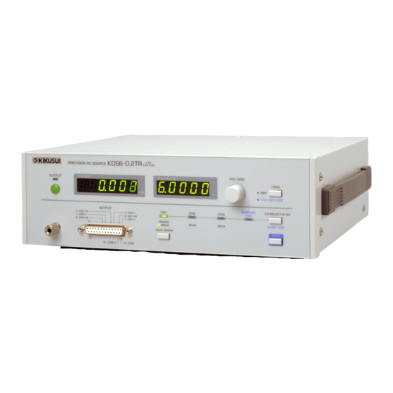
General The KDS6-0.2TR is a low-noise, high-stability three-channel DC voltage source. The KDS6-0.2TR is a precision DC source designed for use on the production and inspection lines of electronic devices, including today’s popular low-voltage, low- current high-frequency parts, as well as ICs, LSIs, and sensors. - Page 12 8 Introduction KDS6-0.2TR...
-
Page 13: Chapter 1 Prior To Use
Unpacking Check As soon as you receive delivery of the KDS6-0.2TR, check to make sure that all of the required accessories are included, and that the KDS6-0.2TR and accessories are free from damage. Fig. 1-1 provides a list of accessories. -
Page 14: Precautions In Setup
Storage temperature range: -10°C to +60°C ■ Avoid high humidity. Do not install the KDS6-0.2TR in a highly humid location such as near a water heater, humidifier, water appliance or the like. Operating humidity range: 20% to 85% RH (without condensation) Storage humidity range: below 90% RH (without condensation) Condensation may take place even when the KDS6-0.2TR is operated within the... -
Page 15: Precautions In Transportation
If the KDS6-0.2TR is moved to a new location or otherwise transported, please observe the following: ■ Turn off the power switch located on the rear panel. Moving the KDS6-0.2TR with the power turned on could result in electric shock or malfunction. ■ Remove all connected wiring. -
Page 16: Checking The Input Power And Fuse
Checking the Input Power and Fuse The KDS6-0.2TR can be operated within one of the four input voltage ranges indi- cated in Table 1-1. Check to determine whether the factory-set voltage range corre- sponds to the voltage you intend to supply to the KDS6-0.2TR. Additionally, the input fuse rating must be compatible with the selected input voltage range. -
Page 17: Connecting The Power Cord
Connecting the Power Cord Connect the power cord to the KDS6-0.2TR. Insert the 3-pole plug with ground on the cord supplied with the KDS6-0.2TR into an outlet. The KDS6-0.2TR is designed for connection to a power supply of Overvoltage Cat- egory II. -
Page 18: Grounding
WARNING • Connect the ground terminal to an adequate earth ground. CAUTION • Failure to connect the KDS6-0.2TR to ground could result in erroneous operation due to external noise, or may increase the noise generated by the KDS6-0.2TR. For your safety, be sure to earth ground the KDS6-0.2TR. -
Page 19: Chapter 2 Names And Functions Of Parts
For more details on the OCP, refer to "OCP function" on page 22. NOTE • The OCP function is activated when an over-range state lasts for approximately 1.5 seconds or longer. [2] Chassis terminal This terminal is connected to the chassis (frame) of the KDS6-0.2TR. KDS6-0.2TR Names and Functions of Parts 15... - Page 20 Adjusts the voltage of the channel currently selected. The faster the knob is turned, the greater the change in voltage value. [9] LOCAL key Pressing this key when the RMT lamp remains lit (i.e., when the KDS6-0.2TR is controlled through GPIB or RS-232C) enables the user to operate the KDS6-0.2TR from the panel.
-
Page 21: Rear Panel
[11] POWER switch Turns the power on ( | ) and off (O). [12] GPIB connector The connector is used to connect the KDS6-0.2TR to a GPIB controller. For details on setting the address, refer to 4.1.1, "GPIB Interface." [13] RS-232C connector The connector is used to control the KDS6-0.2TR remotely through a computer,... - Page 22 18 Names and Functions of Parts KDS6-0.2TR...
-
Page 23: Chapter 3 Basic Operations And Connections
When the KDS6-0.2TR is switched on, the setting values specified in Table 3-1 are displayed. The KDS6-0.2TR is shipped from the factory with the setting values shown in Table 3-1. Setting values marked as “Enabled” under “Backup” in the table are saved in the internal memory (powered by an internal battery). -
Page 24: Basic Operations
LED is off, the 10-mA range is enabled. RANGE key The RANGE key is active only when Channel 1 is selected. Channels 2 and 3 work the 30-mA range only. 20 Basic Operations and Connections KDS6-0.2TR... - Page 25 SHIFT + LOCAL keys In key lock status, the “KEY LOCK” LED remains lit. ■ Clearing the key lock status With the SHIFT key held down, press the LOCAL key continuously for 0.5 seconds or longer. KDS6-0.2TR Basic Operations and Connections 21...
- Page 26 OCP function has activated. ■ Clearing OCP Press the OUTPUT key. Before pressing the OUTPUT key, make sure to eliminate the cause of OCP activation. 22 Basic Operations and Connections KDS6-0.2TR...
-
Page 27: Connection To The Load
The KDS6-0.2TR employs a D-Sub 25-pin female connector for the output connec- tor. To connect the KDS6-0.2TR to its load, connect to the output with the D-Sub 25-pin male connector supplied, using Table 3-2 as a guide. Table 3-2 Output connector pin assignment... - Page 28 CH1+/CH1+ S Load resistance of these cables translates CH2+/CH2+ S Load into voltage error. CH3+/CH3+ S Load Sensing point located far from the load Fig. 3-2 Connection to the load (example of poor cabling) 24 Basic Operations and Connections KDS6-0.2TR...
-
Page 29: About The Load
About the Load Unlike other general DC power supplies, the KDS6-0.2TR is optimized as a low- noise voltage source. For this reason, the KDS6-0.2TR is not suitable for use in applications intended to drive loads with abruptly changing current. If the peak current is lower than the maximum permissible current for each channel, the KDS6-0.2TR may be used without activating the OCP function. - Page 30 26 Basic Operations and Connections KDS6-0.2TR...
-
Page 31: Chapter 4 Remote Control
Remote Interfaces The KDS6-0.2TR is equipped with the GPIB and RS-232C remote interfaces. When either the GPIB or the RS-232C interface is used, the KDS6-0.2TR can be controlled from an external controller in conjunction with programming. The GPIB and RS-232C interfaces cannot be used simultaneously. -
Page 32: Rs-232C Interface
Stop bit XON/XOFF Flow control *1. The KDS6-0.2TR was factory-shipped with the bit rate set to 19200 bps. To change the bit rate, follow the procedure described below. *2. This setting is fixed. Set the PC to be used accordingly. - Page 33 Transmission control from the RS-232C terminal to the KDS6-0.2TR Pause Resume transmission Within 3 characters After receiving DC3, the KDS6-0.2TR pauses transmission within 3 characters. Transmission control from the KDS6-0.2TR to the RS-232C terminal Pause Resume transmission Within 10 characters The RS-232C terminal must pause transmission within 10 characters after receiving DC3.
-
Page 34: Messages And Terminators
Occurrence of error such as a syntax error A SILent command message can be used to specify whether or not an acknowledge message should be returned. The KDS6-0.2TR is initially set not to return the acknowledge message. 30 Remote Control... -
Page 35: Terminators
CR+LF (ASCII:0Dh, 0Ah) is used. In the case of GPIB, EOI is then sent. Device Messages The program messages and response messages supported by the KDS6-0.2TR are collectively referred to as “device messages.” Each of the device messages is explained below. - Page 36 0.0000 V Channel selection Channel 1 Channel-1 range 200 mA Output ammeter sampling rate Normal mode OUTPUT KEYLOCK Clear GPIB addresses, RS-232C bit rates, and settings performed via SILent and *SRE device messages are not initialized. 32 Remote Control KDS6-0.2TR...
- Page 37 Program message • Syntax Query message: *IDN? Response message In response to *IDN?, the model name, version no., etc., are returned as shown in the example below: KIKUSUI ELECTRONICS CORP., KDS6-0.2TR,0, 1.00 Company name Model name Version No. Not in use ERR? Inquires about the contents of an error register.
- Page 38 Minimum value Maximum value Resolution Data format Integer Initial value (Example) To enable all service request factors: *SRE 9 Response message In response to *SRE?, the present setting is returned as an integer (0 - 255). 34 Remote Control KDS6-0.2TR...
- Page 39 The RQS bit (bit 6) of a status byte register is cleared when serial polling is exe- cuted or the power is turned off and on again. Program message • Syntax Command message: *CLS KDS6-0.2TR Remote Control 35...
- Page 40 Unit (Example) To set the voltage value of Channel 1 to 3.1234 V: V1Set 3.1234 Response message In response to V1S?, the present setting is returned as fixed decimal point data (0.0000 to 6.5000). (Example) 3.1234 36 Remote Control KDS6-0.2TR...
- Page 41 In response to VSET?, the present settings of the channels are delimited with “,” (ASCII:2Ch) and returned as fixed decimal point data (0.0000 to 6.5000). The data is returned in the order of CH1, CH2, and CH3. (Example) 2.80001,1.0000,0.5000 KDS6-0.2TR Remote Control 37...
- Page 42 If OCP has occurred, CH<n>OCP (n = 1 to 3) is returned, “n” indicating the channel in which OCP took place. To clear OCP, the OUTP 0 command is sent. (Example 1) 30.0000 (Example 2) CH2 OCP 38 Remote Control KDS6-0.2TR...
- Page 43 If OCP has occurred, CH<n>OCP (n = 1 to 3) is returned, “n” indicating the channel in which OCP took place. To clear OCP, the OUTP 0 command is sent. (Example 1) 200.000,10.3245,-0.0005 (Example 2) CH1 OCP,CH1 OCP,CH1 OCP KDS6-0.2TR Remote Control 39...
- Page 44 * The setting is reset to 0 when the power is turned off. (Example) To set to turn output on: OUTP 1 Response message In response to OUT?, the present setting is returned as a character (1 or 0). (Example) To turn output on: To turn output off: 40 Remote Control KDS6-0.2TR...
- Page 45 (Example) To set the current range of Channel 1 to 10 mA: RANG 0 Response message In response to RANG?, the present setting is returned as an integer (0 or 1). (Example) When Channel-1 current range is 10 mA: When Channel-1 current range is 200 mA: KDS6-0.2TR Remote Control 41...
- Page 46 In response to SAMP?, the present setting is returned as an integer (1 or 0). (Example) In high-speed mode: In normal mode: NOTE: When the sampling rate is set to the high-speed mode, the current measuring resolution will be 5 digits. 42 Remote Control KDS6-0.2TR...
- Page 47 (Example) To set to turn the KEYLOCK on: KEYL 1 Response message In response to KEYL?, the present setting is returned as an integer (1 or 0). (Example) When KEYLOCK is on: When KEYLOCK is off: KDS6-0.2TR Remote Control 43...
- Page 48 (Example) To perform the setting that will not allow switchover: ACHSel 0 Response message In response to ACHS?, the present setting is returned as an integer (1 or 0). (Example) When panel indication switchover is on: When panel indication switchover is off: 44 Remote Control KDS6-0.2TR...
-
Page 49: Message Table
Resolution Unit SILent OFF(0) ON(1) – – Acknowledge message (RS-232C) *RST – – – – Device initialization (resets to factory-settings) “KIKUSUI ELECTRONICS CORP.,KDS6-0.2TR,0,x.xx” *IDN? – – – – is returned. (x.xx is the version No.) ERR? – – – –... - Page 50 — To the present users of the existing KIKUSUI Model SPEC40080 — The KDS6-0.2TR supports the following device messages used by the existing KIKUSUI Model SPEC40080. Present users of the SPEC40080 can operate The KDS6-0.2TR without modifying the program. VSET<n>...
-
Page 51: Chapter 5 Maintenance And Calibration
This chapter explains the maintenance and calibration of the KDS6-0.2TR. To maintain initial performance longer, perform maintenance and calibration on a peri- odic basis. Cleaning • When cleaning the KDS6-0.2TR, be sure first to turn the POWER switch WARNING off and to unplug the power cord. CAUTION •... - Page 52 48 Maintenance and Calibration KDS6-0.2TR...
-
Page 53: Chapter 6 Specifications
In normal mode: In high-speed mode: 1 μA Accuracy of current indication ±(0.2 % of rdg + 20 digits) Panel Voltage 7-segment LED: 5 digits indication Current 7-segment LED In normal mode: 6 digits In high-speed mode: 5 digits KDS6-0.2TR Specifications 49... -
Page 54: General Specifications
Pollution degree 2 *1. Not applicable to custom-made products and modified products. *2. This is a Class I equipment. Be sure to ground the KDS6-0.2TR's protective conductor terminal. The safety of this product is only guaranteed when the product is properly grounded. -
Page 55: Accessories
All functions available except for listen-only function Service request All functions available Remote local All functions available Parallel pole No function available Device clear All functions available Device trigger No function available Controller No function available Electrical interface Open collector KDS6-0.2TR Specifications 51... -
Page 56: Outline And Dimensions
Outline and Dimensions MAX10 MAX20 MAX330 MAX305 Units: mm Fig. 6-1 KDS6-0.2TR Outline Diagram 52 Specifications KDS6-0.2TR... -
Page 57: Index
LOCAL key - - - - - - - - - - - - - - - - - - - - - - - - - 15 voltage setting display - - - - - - - - - - - - - - - - - - 15 KDS6-0.2TR Index 53... - Page 58 54 Index KDS6-0.2TR...
- Page 60 KIKUSUI ELECTRONICS CORP. 1-1-3 Higashiyamata, Tsuzuki-ku, Yokohama, 224-0023, Japan Phone: +81-45-482-6353 Facsimile: +81-45-482-6261 www.kikusui.co.jp/en/...
Need help?
Do you have a question about the KDS6-0.2TR and is the answer not in the manual?
Questions and answers