Table of Contents
Advertisement
Quick Links
See also:
Manual
User's Manual
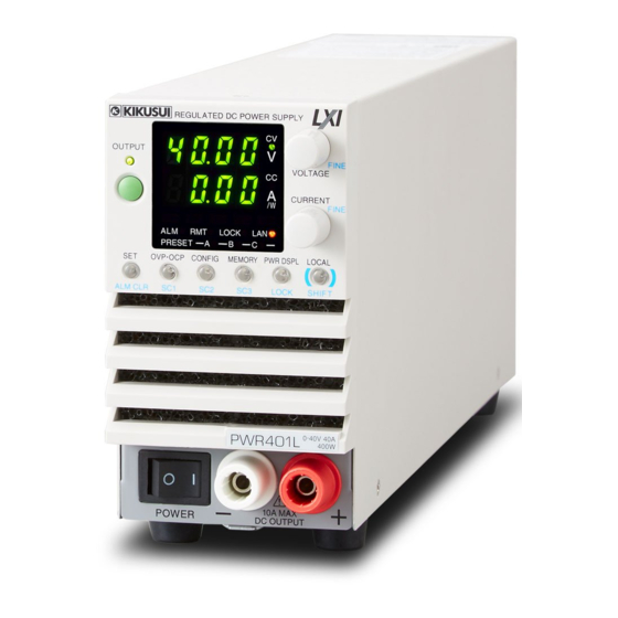
Regulated DC Power Supply
PWR-01 Series
400W model
PWR401L
PWR401MH
800W model
PWR801L
PWR801MH
1200W model
PWR1201L
PWR1201MH PWR1201H
PART NO. IB031113
Aug. 2017
PWR401ML
PWR401H
PWR801ML
PWR801H
PWR1201ML
Component Names 8
Connecting to the Output Terminals
Measured Value Display and Setting Display
CV Power Supply and CC Power Supply
Using the PWR-01 as a CV or CC Power
Protection functions and Alarms
Preset Memory function
Locking Panel Controls (Key Lock)
CONFIG Shortcut function
Switching from Remote Mode to Local Mode
Advanced Features 75
Bleeder Circuit function
Variable Internal Resistance function
Sequence function
Synchronized Operation
External Control 83
Product Operation
About the J1/ J2 Connectors
Notes for Connecting External Voltage (Vext)
Output voltage control
Output Current Control
Controlling the Output On and Off States
Controlling Output Shutdown
Controlling the Clearing of Alarms
External Monitoring
Parallel/ Series Operation 101
Master-Slave Parallel Operation
Series operation
Common specifications
14
18
20
22
24
28
30
34
36
37
41
43
45
Supply
46
54
CONFIG Settings
70
71
72
73
76
78
79
80
84
85
88
90
92
94
96
97
98
102
108
Maintenance 113
114
Calibration
116
Cleaning
Specifications 117
119
400W model
122
800W model
125
1200W model
128
Appendix135
Advertisement
Table of Contents

Related Manuals for Kikusui PWR401L


Summary of Contents for Kikusui PWR401L
-
Page 1: Table Of Contents
Protection functions and Alarms PWR-01 Series CONFIG Settings Preset Memory function 400W model Locking Panel Controls (Key Lock) CONFIG Shortcut function PWR401L PWR401ML Switching from Remote Mode to Local Mode PWR401MH PWR401H Advanced Features 75 Bleeder Circuit function 800W model... -
Page 2: About The Pwr-01 Manuals
DC power supplies. © 2017 Kikusui Electronics Corporation PWR-01 manual construction User’s manual (this manual, PDF) Accessories This manual is intended for first-time users of this product. -
Page 3: Product Overview
(OCP) from being activated. 400W model 800W model 1200W model L type Bleeder circuit function PWR401L PWR801L PWR1201L (40 V) You can turn the bleeder circuit on and off. Turn the bleeder ML type circuit off when you do not want the internal bleeder circuit... -
Page 4: Safety Precautions
Notations Used in This Manual Safety Precautions When using this product, be sure to observe the “Safety • In this guide, the suite of products shown on the front cover is also referred to as the “PWR-01.” Precautions” in the Safety Information manual. •... - Page 5 Contents Setting limits ........CONFIG Settings ........CONFIG parameter details....Preset Memory function ......About the PWR-01 Manuals ....2 Saving settings ........Accessories ...........2 Recalling settings ........ Product Overview ........3 Locking Panel Controls (Key Lock) .... Features ..........3 CONFIG Shortcut function ......Safety Precautions .........4 Registering CONFIG shortcuts....
- Page 6 Setting..........Starting series operation ....Maintenance Calibration..........Calibration overview......Calibration procedure......Cleaning............ Specifications 400W model..........800W model..........1200W model........... Common specifications......A Factory Default Settings Appe ..136 B Options ........138 ndix C Troubleshooting ......140 PWR-01...
- Page 7 This page is intentionally blank. PWR-01...
-
Page 8: Component Names
Component Names Front panel REGULATED DC POWER SUPPLY Controls OUTPUT Controls FINE VOLTAGE REGULATED DC POWER SUPPLY CURRENT FINE DLY SEQ LOCK LOCK PRESET OUTPUT OVP•OCP CONFIG MEMORY PWR DSPL LOCAL FINE VOLTAGE ALM CLR LOCK SHIF T CURRENT FINE DLY SEQ LOCK LOCK... - Page 9 Name Function POWER switch Press the ( ) side to turn on and the ( ) side to turn off. p.28, p.29 Voltmeter Displays the voltage, alarm, or CONFIG parameter number. p.34, p.54 Lights green when output is turned on. Blinks orange during output-on delay. Blinks p.37 green during output-off delay.
- Page 10 Rear Panel 400W model 800W model 1200W model PWR-01...
- Page 11 Name Function DC OUTPUT terminal Rear-panel output terminal. p.24 Chassis terminal A connector for grounding the output. p.24 Ethernet port for controlling the PWR-01 remotely. LAN port RS232C port for controlling the PWR-01 remotely. RS232C/ TRG IN Trigger signal input connector. The common terminal is connected to the connector chassis.
- Page 12 This page is intentionally blank. PWR-01...
-
Page 13: Installation And Preparation
Installation and Preparation This chapter describes how to turn on the PWR-01, what kind of load cables to use, and how to connect cables to the output terminals. -
Page 14: Connecting The Power Cord
Connecting the Power Cord This product conforms to IEC Overvoltage Category II (energy-consuming equipment that is supplied from a fixed installation). Risk of electric shock. WARNING • This product conforms to IEC Safety Class I (equipment that has a protective con- ductor terminal). -
Page 15: 1200W Model
Installation and Preparation | Connecting the Power Cord 1200W model Risk of electric shock. WARNING • Before you connect the power cable, turn off the switchboard breaker (a switch that cuts off the power supply from the switchboard). Risk of fire. •... -
Page 16: Connection Procedure
Installation and Preparation | Connecting the Power Cord 400W model 800W model 1200W model Protective conductor current 1.5 mA 2.5 mA 4.0 mA (at 265 Vac, 60 Hz) Inrush current 25 Amax 50 Amax 75 Amax Necessary cable Vinyl cabtire cable (VCTF): Nominal cross-sectional area 5.5 mm 3 core Finished diameter: 12.1 mm or less Rated voltage: 250 V or higher... - Page 17 Installation and Preparation | Connecting the Power Cord Attach the core as close to the input terminal as possible but not too close as to get in the way of attaching and removing the INPUT terminal cover. Use the cable tie to fix the core on to the power cord. Check that the core is locked and does not move.
-
Page 18: Load Considerations
Load Considerations Note that the output will become unstable if the following types of loads are connected. Loads with peak current or pulse-shaped current The PWR-01 only indicates mean values. Even when the indicated value is less than or equal to the set constant current, the peak values may exceed the set constant current. - Page 19 Installation and Preparation | Load Considerations Loads with accumulated energy Connecting a load with accumulated energy, such as a battery, to the PWR-01 may cause current to flow from the load to the internal circuit of the PWR-01. This current may damage the PWR-01 or reduce the life of the load.
-
Page 20: Selecting The Load Cables
+ (positive) and - (negative) output wires of the load cable side by side or bundling them together is more effective against unwanted noise. The Kikusui-recommended currents shown in the above table are allowable currents that have been reduced in consideration of the potential bundling of load cables. - Page 21 Installation and Preparation | Selecting the Load Cables Limitations of the remote sensing function All wires have resistance. As the wire becomes longer or the current becomes larger, the volt- age drop in the wire becomes greater. This results in a smaller voltage being applied at the load end.
-
Page 22: Output Terminal Insulation
Output Terminal Insulation Risk of electric shock. For safety reasons, even if the output terminal is grounded, WARNING make sure that the insulation capacity of the output terminal (including the sensing terminal) is greater than or equal to the isolation voltage of this product. For details on the isolation voltage of each model, see "Specifications"... -
Page 23: When The Output Terminal Is Grounded
Installation and Preparation | Output Terminal Insulation When the output terminal is grounded If the positive output terminal is connected to the chassis terminal, the positive output termi- nal is at ground potential. The cable and load that are connected to the output terminal (including the sensing terminal) will only require an insulation capacity that is greater than or equal to the maximum output voltage of the PWR-01 with respect to the chassis. -
Page 24: Connecting To The Output Terminals
Connecting to the Output Terminals Risk of electric shock. WARNING • Turn the POWER switch off before you touch the rear-panel output terminals. • Even if you turn the output off or turn the POWER switch off, if the bleeder circuit is set to off (CF01: DIS), the voltage that was present when the output was on will remain at the output terminals. - Page 25 Installation and Preparation | Connecting to the Output Terminals Connect the load cables to the rear-panel output terminals. Use the included screw set. Memo To reduce the influence of noise on the output, keep the cables as short as possible. If If you do not connect load possible, twist the positive and negative load cables.
- Page 26 Installation and Preparation | Connecting to the Output Terminals Attach the adapter to the top half of the OUTPUT terminal cover. Memo Insert the adapter tabs into the cuts in the OUTPUT terminal cover. The top and bottom halves of the OUTPUT For thin load cables terminal cover have Cable diameter...
-
Page 27: Connecting To The Front-Panel Output Terminals
Installation and Preparation | Connecting to the Output Terminals Connecting to the front-panel output terminals The specifications of the PWR-01 apply to the rear-panel output terminals. The front-panel output terminals may not meet the specifications. There is no grounding terminal on the front-panel output terminals. To ground one side of the output, connect the rear-panel chassis terminal to either the negative output terminal or the positive output terminal. -
Page 28: Turning The Power On
Turning the Power On Turning on the POWER switch Risk of electric shock. Regardless of whether load cables are connected to the output WARNING terminals, be sure to attach the OUTPUT terminal cover before turning the POWER switch on. Risk of damage to load. CAUTION If the PWR-01 is configured to turn on the output when the POWER switch is turned on in CONFIG settings, set an appropriate OVP or OCP value before connecting a different load. -
Page 29: Turning The Power Switch Off
Installation and Preparation | Turning the Power On Turning the POWER switch off Turn the POWER switch off ( ). The PWR-01 saves the panel settings (except the output on/off setting) that were in use immediately before the POWER switch was turned off. You can use the CONFIG settings (CF45) to select the output state of the PWR-01 when the POWER switch is turned on (p.65). -
Page 30: Remote Sensing Function
When the sensing terminals are not used, connect the sens- ing short bar. E3-200-546 If the short bar is damaged or lost, contact your Kikusui agent or distributor. Connecting the sensing cables Risk of electric shock and damage to internal circuits. - Page 31 Installation and Preparation | Remote Sensing function If the sensing cables come loose, the output voltage will rise several volts. To prevent voltage output exceeding the voltage setting, set an appropriate OVP trip point. After you finish using remote sensing, connect the sensing short bar. PWR-01 Output terminal Capacitor...
- Page 32 Installation and Preparation | Remote Sensing function Electrolytic capacitor to connect across the load If the wiring inductance component is large, the following symptoms may appear. • Oscillation If the wires used to connect to the load are long, the wiring inductance and capacitance can cause phase shifting at a level that cannot be ignored.
-
Page 33: Basic Features
Basic Features This chapter describes how to turn the out- put on and off and the basic operations that you can perform from the front panel. -
Page 34: Measured Value Display And Setting Display
Measured Value Display and Setting Display The voltage and current displays have the following two states. • Measured value display • Setting display In addition to the voltmeter and ammeter, the PWR-01 can display the power, the set OVP, OCP, or UVL, and the system configuration. Measured value display The present output voltage and output current are displayed. - Page 35 Basic Features | Measured Value Display and Setting Display System configuration setting display Press CONFIG to light the key and display the current system REGULATED DC POWER SUPPLY configuration settings. OUTPUT FINE VOLTAGE CURRENT FINE DLY SEQ LOCK LOCK PRESET OVP•OCP CONFIG...
-
Page 36: Panel Operations
Panel Operations Measured value display, setting display, and set OVP/ OCP display Turn the VOLTAGE knob to change the voltage. Turn the CURRENT knob to change the current. Decrease Increase REGULATED DC POWER SUPPLY When the output is on, press SET to switch to the setting dis- OUTPUT FINE VOLTAGE... -
Page 37: Output Operation
Output Operation The output turns on and off each time that you press OUTPUT. When output is on, the OUT- PUT LED lights. When the output is off, the OUTPUT LED turns off. When the output is on, output is generated at the present set values. If you change the settings while the output is on, the changes are applied immediately to the output. -
Page 38: Output-On/ Off Delay Setting
Basic Features | Output Operation Output-on/ off delay setting You can set the delay from when the OUTPUT key is pressed to when the output actually turns on or off (p.59). This is a useful feature when you want to turn the output on or off by setting a delay according to the load characteristics. -
Page 39: Soft Start/ Stop Function
Basic Features | Output Operation Soft start/ stop function You can set the rise time and fall time of output current. This is useful when the load cannot follow the sudden rise or fall in the output current or when you want to avoid the overcurrent protection from being activated. - Page 40 Basic Features | Output Operation Soft start and soft stop waveforms Waveforms when soft start and soft stop are used are shown below. Waveform when soft start is used [Voltage (V)] Outpu on: Output voltage 5 V Soft start time: 5.0 s (CF06: 5.0) [Time (s)] 10.0...
-
Page 41: Operation Overview
105 % of the rated output power), and the output voltage and output current change depending on the load value. [L type] Operating range Rated output voltage: 40 V Rated output power Rated output power PWR401L: 400 W PWR801L: 800 W PWR1201L: 1200 W Rated output current PWR401L PWR801L... - Page 42 Basic Features | Operation Overview [MH type] Operating range Rated output voltage: 240 V Rated output power PWR401MH: 400 W Rated output power PWR801MH: 800 W PWR1201MH: 1200 W Rated output current PWR401MH PWR801MH PWR1201MH 10.5 13.5 16.5 Output current (A) [H type] Operation range Rated output voltage: 650 V Rated output power...
-
Page 43: Cv Power Supply And Cc Power Supply
CV Power Supply and CC Power Supply The PWR-01 has features that makes it possible to function as a constant-voltage source and constant-current source even when the load is changed. The constant-voltage source opera- tion is referred to as constant-voltage (CV) mode. The constant-current source operation is referred to as constant-current (CC) mode. - Page 44 Basic Features | CV Power Supply and CC Power Supply CV mode and CC mode operation example This section uses a power supply with a rated output voltage of 100 V and a rated output cur- rent of 10 A as an example. A load resistance (R ) of 8 Ω...
-
Page 45: Using The Pwr-01 As A Cv Or Cc Power Supply
Press SET to change to the setting display. The SET key lights. Turn the VOLTAGE knob to set the voltage. Voltage setting range: 0 % to 105 % of the rated output voltage PWR401L 0 V to 42 V PWR801L 0 V to 42 V... -
Page 46: Protection Functions And Alarms
For shutdown (SD) and master-slave parallel operation (PRL ALM), use method “b” to clear the alarm. If an alarm still occurs even after you have corrected all the causes of alarms, the PWR-01 may be malfunctioning. Stop using it immediately, and contact your Kikusui agent or distribu- tor. PWR-01... -
Page 47: Setting The Protection Functions
Basic Features | Protection functions and Alarms Alarm signal Alarm signal is generated from pin 14 of the J1 connector if PRL ALM or SD is activated. The J1 connector is at approximately the same electric potential as the negative output terminal. Alarm signal is generated from pin 4 of the J2 connector if OVP, OCP, FOCP, OHP, SENSE, AC-FAIL, WATCHDOG, or SD is activated. - Page 48 Basic Features | Protection functions and Alarms Checking OVP operation If the voltage setting limit is set to on (CF23: ON), the output voltage cannot be set higher than the OVP trip point, so you cannot verify the OVP operation. Check that the OUTPUT LED is turned off.
-
Page 49: Checking Ocp Operation
Basic Features | Protection functions and Alarms Turn the CURRENT knob to set the OCP trip point. OCP setting range: 10 % to 112 % of the rated output current L type ML type MH type H type 400 W 4 A to 44.8 A 2 A to 22.4 A 0.5 A to 5.6 A... - Page 50 Basic Features | Protection functions and Alarms Front-panel output terminal overcurrent protection (FOCP) Front-panel output terminal overcurrent protection (FOCP) is activated when the output cur- rent from the front-panel output terminal exceeds 10 A (typical value). The trip point is fixed. If the FOCP trip point is lower than the OCP trip point, OCP is prioritized.
- Page 51 Basic Features | Protection functions and Alarms Communication monitoring (WATCH The watchdog function monitors the SCPI command communication status. Communication is assumed to have stopped if there is no communication within the time period specified by the communication monitoring timer setting (CF21). The function operates regardless of whether the product is in remote or local (panel control) mode.
-
Page 52: Setting Limits
Basic Features | Protection functions and Alarms Setting limits Voltage setting limit The maximum voltage that can be set is limited to about 95 % of the OVP trip point to prevent OVP activation due to mistaken operations. By factory default, the voltage setting limit is set to on (CF23: ON). The voltage setting limit (CF23) on/ off state is synchronized to undervoltage limit (UVL). - Page 53 Basic Features | Protection functions and Alarms Current setting limit The maximum current that can be set is limited to about 95 % of the OCP trip point to prevent OCP activation due to mistaken operations. By factory default, the current setting limit is set to on (CF22: ON). If you enable the current setting limit when the current setting is higher than 95 % of the OCP trip point, the current setting is retained, but the OCP trip point is changed to 105 % of the current setting.
-
Page 54: Config Settings
CONFIG Settings Use the CONFIG settings to set the PWR-01 system configuration. You can set and display the following parameters in the CONFIG settings. ● Effect: indicates that the parameter is affected when the panel settings are reset (CF00). ■ indicates that the parameter may be affected when the LAN interface settings are reset (CF60: LCI/ DEF). - Page 55 Basic Features | CONFIG Settings Display Parameter Mnemonic Setting/ display Effect Note switching number — — CF50 Ip addr. 1 IP address display (1) — — CF51 Ip addr. 2 IP address display (2) CF52 Ip addr. 3 IP address display (3) —...
- Page 56 Basic Features | CONFIG Settings CONFIG key Measured value display Mnemonic display CONFIG key Basic settings CF00 CF01 VOLTAGE knob VOLTAGE knob OFF. D LOCAL key CF09 CONFIG key CF10 E. C C Basic settings (external) E. C V CF11 VOLTAGE knob VOLTAGE knob CF19...
- Page 57 Basic Features | CONFIG Settings Displaying and setting CONFIG parameters CF00, CF60, and CF80 are execution parameters of features. For the execution procedure, see the details of each CONFIG parameter. REGULATED DC POWER SUPPLY Parameter number VOLTAGE knob CF (CONFIG) + a Select the parameter number.
-
Page 58: Config Parameter Details
Basic Features | CONFIG Settings CONFIG parameter details The details of CONFIG parameters are provided below. CF00 (RST) Resets the panel settings Select this to set the following parameters to their factory default settings (p.136). Then, press SET twice to execute the reset. •... - Page 59 Basic Features | CONFIG Settings CF03 (VIR) Internal resistance setting (VIR) Sets the internal resistance (Rint) (p.78). The internal resistance setting range (p.78) varies depending on the model. Display Description Variable internal resistance function is not used (factory default setting). Rint (min) to Rint (max) Rint (min) Ω...
- Page 60 Basic Features | CONFIG Settings CF09 (OFF. D ) Output-off delay setting You can set the delay from when the OUTPUT key is pressed to when the output actually turns off (p.38). Display Description 0. 0 No delay (factory default setting) 0.
- Page 61 Basic Features | CONFIG Settings CF15 (E. L OG) External control logic for turning output on/ off Sets the logic that is used for output on/ off control using an external contact (p.94). Display Description The output is turned on with a low signal (0 V to 0.5 V) or short cir- cuit (factory default setting).
- Page 62 Basic Features | CONFIG Settings CF21 (WDOG) Communication monitoring (WATCHDOG) timer Sets the interval for monitoring SCPI command communication (p.51). The communication monitoring operates regardless of whether the product is in remote or local (panel control) mode. If you are not using remote control (commands), set this to “OFF”. Display Description Communication monitor timer is set to off (factory default setting).
- Page 63 Basic Features | CONFIG Settings CF32 (SC3) CONFIG parameter shortcut registration (SC3) Registers a CONFIG setting parameter to the front panel’s SC3 key (p.72). Display Description CONFIG parameter not registered (factory default setting) 01 to 99 01 to 99 CF01 to CF99 CF33 (BEEP) Buzzer on/ off Turns the buzzer on and off.
- Page 64 Basic Features | CONFIG Settings CF41 (USB) USB interface setting Enables or disables the USB interface. By setting this parameter to “OFF,” you can disable the USB interface function even when a USB cable is connected. This parameter is applied when you turn the POWER switch off and on. Display Description USB disabled...
- Page 65 Basic Features | CONFIG Settings CF45 (PON) Output state at power-on Sets the output condition that the PWR-01 will be in when the power is turned on (p.28). When you are using an external contact to turn the output off, this parameter is invalid. This parameter is applied when you turn the POWER switch off and on.
- Page 66 Basic Features | CONFIG Settings CF60 (BOOT) LAN setting reset (LCI/ dEF)/ apply (APPL) Sets whether to reset or apply the LAN interface settings (p.57). Then, press SET twice to execute the reset or application. If you select to reset the LAN interface settings (LCI (LCI)/ DEF (Default)), the security password will be cleared, and the PWR-01 will be in a security-disabled state.
- Page 67 Basic Features | CONFIG Settings CF66 (SUB) IP address subnet mask If you want to set the IP address manually (MANUAL IP), set the subnet mask prefix. To do so, use CF61 to set MANUAL IP to on. This parameter is applied when you turn the POWER switch off and on or when you execute APPL (Apply) with CF60.
- Page 68 Basic Features | CONFIG Settings CF72 (BAUD) RS232C baud rate Sets the baud rate of the RS232C interface. This parameter is applied when you turn the POWER switch off and on. Display Baud rate 1. 2 1200 bps 2. 4 2400 bps 4.
- Page 69 Basic Features | CONFIG Settings CF83 (TRG. I ) Trigger input signal polarity Sets the polarity of the trigger input signal. Trigger signals are used to resume a sequence step and to perform synchronized operation. Display Description Positive Trigger Positive trigger (factory default setting) Negative Trigger Negative trigger CF84 (TRG.
-
Page 70: Preset Memory Function
Preset Memory function There are three preset memory entries for saving combinations of voltage, current, OVP, OCP, and UVL settings. Saved settings can be recalled from the preset memory when needed. Saving settings Set the voltage, current, OVP, OCP, and UVL to the values you want to save. -
Page 71: Locking Panel Controls (Key Lock)
Locking Panel Controls (Key Lock) The key lock function is available to prevent the settings from being changed by mistake. REGULATED DC POWER SUPPLY OUTPUT FINE VOLTAGE When the keys are locked (when the LOCK LED is lit), only the CURRENT OUTPUT key is valid. -
Page 72: Config Shortcut Function
CONFIG Shortcut function There is a CONFIG shortcut function that allows up to three CONFIG parameters of your choice (SC1, SC2, and SC3) to be registered. Registered CONFIG parameters can be recalled with the SC key without having to enter the CONFIG menu. Registering CONFIG shortcuts Press CONFIG four times (CF30). -
Page 73: Switching From Remote Mode To Local Mode
Switching from Remote Mode to Local Mode When the PWR-01 is being controlled remotely, the RMT LED in the display area lights. REGULATED DC POWER SUPPLY OUTPUT FINE VOLTAGE To switch the PWR-01 to local mode from the front panel, press CURRENT LOCAL. - Page 74 This page is intentionally blank. PWR-01...
-
Page 75: Advanced Features
Advanced Features This chapter describes advanced operations such as the bleeder circuit function, variable internal resistance function, sequence function and synchro- nized operation. -
Page 76: Bleeder Circuit Function
Vout= Output terminal voltage Sink current Model Bleeder circuit 5 Vout 10 Vout 15 Vout 20 Vout 30 Vout 40 Vout PWR401L 0.000 A 0.000 A 0.001 A 0.001 A 0.002 A 0.003 A Normal bleeder 0.381 A 0.347 A 0.312 A... -
Page 77: Bleeder Circuit Function
Advanced Features | Bleeder Circuit function Vout= Output terminal voltage Sink current Model Bleeder circuit 5 Vout 10 Vout 20 Vout 40 Vout 60 Vout 80 Vout PWR401ML 0.000 A 0.000 A 0.000 A 0.001 A 0.001 A 0.002 A Normal bleeder 0.376 A 0.360 A... -
Page 78: Variable Internal Resistance Function
Vrtg: rated output voltage, Irtg: rated output current, Rint: internal resistance 0 <Rint (min) ≤Rint (max) L type, ML type: Rint (max)= Vrtg/ Irtg MH type, H type: Rint (max)= Vrtg/ Irtg x 3/4 PWR401L PWR401ML PWR401MH PWR401H Vrtg [V] Irtg [A] 1.85... -
Page 79: Sequence Function
Sequence function The sequence function enables you to automatically execute programs that you have set in advance one operation at a time. You cannot configure sequence programs from the panel. Programs are created using com- mands. Once a sequence program is executed through remote control, the program is written in the PWR-01, and you can execute this program from the panel. -
Page 80: Synchronized Operation
Synchronized Operation Synchronized operation is a function that synchronizes settings and the resumption of sequence programs using trigger signals. Different PWR-01 models (e.g., PWR400W and PWR800W) can be mixed and connected. Synchronized operation is also possible in parallel operation. Synchronized operation has the following features. To perform synchronized operation, you need to configure various settings using commands through remote control. - Page 81 Connection Use a standard LAN cable (category 5 and straight) up to 30 m in length to make the connec- tion. If you need to use a LAN cable longer than 30 m, please contact your Kikusui agent or distributor.
- Page 82 Advanced Features | Synchronized Operation Connect all the PWR-01s with LAN cables. External device External device TRG IN TRG OUT RJ45 100 μs External device TRG IN TRG OUT RJ45 Use a RJ45 modular branch splitter for branching. External device TRG IN TRG OUT 800W model connection example 1...
-
Page 83: External Control
External Control This chapter explains external control and external monitoring using the J1 and J2 connectors. -
Page 84: Product Operation
Product Operation The J1 or J2 connector on the rear panel of this product can be used to perform the following external controls. • Output voltage control using external voltage or external resistance • Output current control using external voltage or external resistance •... -
Page 85: About The J1/ J2 Connectors
J1 and J2 connectors. Be sure to attach the cover when you are not using the J1 or J2 connector. If the cover is dam- aged or lost, contact your Kikusui agent or distributor. The connector parts necessary to connect to the J1 and J2... - Page 86 External Control | About the J1/ J2 Connectors J1 connector pin arrangement Pin number positions when you are facing the rear panel Signal name Description J1-1 VPGM Terminal used to control the output voltage with an external voltage or external resistance. 0 V to 5 V;...
- Page 87 External Control | About the J1/ J2 Connectors J2 connector pin arrangement Pin number positions when you are facing the rear panel Signal name Description J2-1 STATUS COM Common for pins 2 to 6. J2-2 OUT ON STATUS Outputs a signal when output is on (output through an open-collector photocoupler). J2-3 PWR ON STATUS Outputs a low level signal when the power is on (output through an open-collector photocoupler).
-
Page 88: Notes For Connecting External Voltage (Vext)
Notes for Connecting External Voltage (Vext) This section contains notes for controlling the output using external voltage (Vext). A GND terminal The electric potential of A GND (J1-5, J1-10, and J1-15) of the J1 connector that Vext is con- nected to varies depending on whether remote sensing is used. •... - Page 89 External Control | Notes for Connecting External Voltage (Vext) System that controls multiple PWR-01s with multiple Vexts Connect the GND (negative) terminals between each Vext, but do not connect the negative CAUTION output terminals between each PWR-01. Not following this rule may cause the system to malfunction or damage the devices.
-
Page 90: Output Voltage Control
Output voltage control This section explains how to control the output voltage using an external voltage (Vext) or an external variable resistor (Rext) of approximately 10 kΩ. If no load is connected, it takes some time for the output voltage to decrease. Risk of electric shock. -
Page 91: Control Using An External Resistance (Rext)
External Control | Output voltage control If you use a shielded cable, connect the shield to the negative output terminal. If the shield needs to be connected to the Vext side, see "Notes for Connecting External Voltage (Vext)"(p.88). Use pins 1 and 5 of the J1 connector. Control using an external resistance (Rext) By using an external resistance (Rext) to change the voltage-divider ratio of the reference voltage (J1-3 REF OUT), you can change the output voltage (Eo) to a value in the range of 0... -
Page 92: Output Current Control
Output Current Control This section explains how to control the output current using an external voltage (Vext) or an external variable resistor of approximately 10 kΩ (Rext). Risk of electric shock. WARNING • Ensure that the insulation of Vext or Rext and the connected cable is greater than or equal to the isolation voltage of the PWR-01. -
Page 93: Control Using An External Resistance (Rext)
External Control | Output Current Control Control using an external resistance (Rext) By using an external resistance (Rext) to change the voltage-divider ratio of the reference voltage (J1-3 REF OUT), you can change the output current (Io) to a value in the range of 0 to the 105 % of the rated output current (Irtg). -
Page 94: Controlling The Output On And Off States
Controlling the Output On and Off States This section explains how to use an external contact to control the output on and off states. Risk of electric shock. WARNING • Ensure that the insulation of external contact (S) and the connected cable is greater than or equal to the isolation voltage of the PWR-01. - Page 95 External Control | Controlling the Output On and Off States If two or more units are floating, and you are using a single external contact to turn output on and off, use a relay or similar device for the external contact signal to isolate the signal trans- mitted to each unit.
-
Page 96: Controlling Output Shutdown
Controlling Output Shutdown This section explains how to use an external contact to turn output off. Risk of electric shock. WARNING • Ensure that the insulation of external contact (S) and the connected cable is greater than or equal to the isolation voltage of the PWR-01. For details on the isolation volt- age of each model, see Chap.7 "Specifications"... -
Page 97: Controlling The Clearing Of Alarms
Controlling the Clearing of Alarms This section explains how to use an external contact to clear alarms. Risk of electric shock. WARNING • Ensure that the insulation of external contact (S) and the connected cable is greater than or equal to the isolation voltage of the PWR-01. For details on the isolation volt- age of each model, see Chap.7 "Specifications"... -
Page 98: External Monitoring
External Monitoring External monitoring of the output voltage and output current The J1 connector has monitor outputs for the output voltage and the output current. You can set the monitor output voltage range using CONFIG settings (CF13). Pin no. Signal name Description J1-5 A GND... - Page 99 External Control | External Monitoring External monitoring of the operating status The J2 connector has status outputs that can be used to externally monitor the operation sta- tus of the PWR-01. The following five items make up the status outputs. The outputs are open collector outputs of photocouplers;...
- Page 100 This page is intentionally blank. PWR-01...
-
Page 101: Parallel/ Series Operation
Parallel/ Series Operation This chapter describes the functions of series operation and the master-slave par- allel operations as well as the connection, setup, and operation procedures. -
Page 102: Master-Slave Parallel Operation
Master-Slave Parallel Operation Master-slave parallel operation is a function used to control a whole parallel-connected sys- tem from a master unit. One unit is the master unit, and other PWR-01s connected in parallel are slave units. The master and slave units must all be the same model. You can use master-slave parallel operation to increase the output current (maximum output current: the rated output current of one unit ×... - Page 103 Parallel/ Series Operation | Master-Slave Parallel Operation External monitoring During parallel operation, do not connect the monitor common cable of the master unit to the CAUTION monitor common cables of the slave units. If the cables connected to the load are discon- nected, the common cables will be damaged.
-
Page 104: Connection
Parallel/ Series Operation | Master-Slave Parallel Operation Connection Connecting the signal cables Use the J1 connector to make the connections for parallel operation. The necessary cables are not included. For details, see "About the J1/ J2 Connectors" (p.85). Example of connecting two slave units Slave unit 1 Master unit OUT ON/OFF CONT... - Page 105 Parallel/ Series Operation | Master-Slave Parallel Operation Connecting the Load Risk of electric shock. Turn the POWER switch off before you touch the output termi- WARNING nals. Attach the OUTPUT terminal cover after you finish wiring the load. • When you ground the output terminals, be sure to connect the same polarity output CAUTION terminals (positive or negative) of the master unit and the slave units to the chassis terminals.
-
Page 106: Setting
Parallel/ Series Operation | Master-Slave Parallel Operation Setting Setting the master unit, the slave units, and the number of units in parallel operation (including the master unit) Turn the output off, and then configure the master unit (CF44: 2 or 3) and the slave units (CF44: SLAV). -
Page 107: Starting Master-Slave Parallel Operation
Parallel/ Series Operation | Master-Slave Parallel Operation Starting master-slave parallel operation Turning on the POWER switch Turn on the master unit’s POWER switch. Turn off the POWER switch of each slave unit. Operate the master unit normally. You cannot perform panel operations on the slave units. Turn output on and off from the master unit. -
Page 108: Series Operation
Series operation Series operation is not possible on the H type (PWR401H, PWR801H, PWR1201H). If WARNING you do, the output will exceed the isolation voltage resulting in a dangerous condi- tion. Up to two PWR-01s whose output is less than 650 V can be connected in series. You cannot perform master-slave series operation. - Page 109 Parallel/ Series Operation | Series operation Remote sensing • If the sensing cables are not connected properly, the load may be exposed to excessive CAUTION voltage, and the PWR-01s may be damaged. • To prevent oscillation, connect an electrolytic capacitor with a capacitance of a few hundred µF to a few ten thousand µF across the load as necessary.
-
Page 110: Connection
Parallel/ Series Operation | Series operation Connection Connecting the Load Risk of electric shock. Turn the POWER switch off before you touch the output termi- WARNING nals. Attach the OUTPUT terminal cover after you finish wiring the load. To prevent oscillation, connect an electrolytic capacitor with a capacitance of a few hundred CAUTION µF to a few ten thousand µF across the load as necessary. -
Page 111: Setting
Parallel/ Series Operation | Series operation Setting Setting the voltage and current Set the voltage and current on each unit. The voltage that is output is the total of the voltages of the two units. Set the current to the same value on the two units. Setting the overvoltage protection (OVP) and overcurrent protec- tion (OCP) In series operation, you have to set the overvoltage protection (OVP) and overcurrent protec-... - Page 112 This page is intentionally blank. PWR-01...
-
Page 113: Maintenance
Maintenance This chapter explains how to perform cali- bration. -
Page 114: Calibration
The product is calibrated before shipment. To maintain long-term reliable performance, we recommend periodic calibration. To have your product calibrated, contact your Kikusui distributor or agent. If you are going to calibrate the product, follow the procedure below. All the calibration param- eters of this product are listed. -
Page 115: Calibration Procedure
Maintenance | Calibration Calibration procedure Use the KIKUSUI PWR-01 Calibration software application in the CD-ROM to calibrate the PWR-01. System requirements for PWR-01 Calibration are as follows: OS • Windows 10 (x86/ x64) • Windows 8.1 (x86/ x64) •... -
Page 116: Cleaning
Cleaning Risk of electric shock. Before you perform maintenance, be sure to turn the POWER WARNING switch off and remove the power plug from the outlet or turn off the switchboard. Cleaning the Dust Filter Dust filters are installed on the inside of the louver on the front panel. Periodically clean the filter to prevent clogging. -
Page 117: Specifications
Specifications This chapter contains the specifications and gives the dimensions of the PWR-01. - Page 118 Specifications | Unless specified otherwise, the specifications are for the following settings and conditions. • Loads are pure resistive loads. • The product is warmed up for at least 30 minutes (with current flowing). • After warm-up, the product must be calibrated correctly in a 23 °C ± 5 °C environment according to the appropriate calibration procedure.
-
Page 119: 400W Model
This section provides the specifications specific to the 400W model. For specifications com- mon to all models (Protection functions, Signal output and input, Control functions, Other functions, Operation display, Interface, and General), see "Common specifications"(p.128). AC input PWR401L PWR401ML PWR401MH PWR401H... - Page 120 Specifications | 400W model Output PWR401L PWR401ML PWR401MH PWR401H Rating 40 V 80 V 240 V 650 V Output voltage 40 A 20 A 1.85 A Output current Output power 400 W Voltage 42 V 84 V 252 V 682.5 V...
- Page 121 Specifications | 400W model Display function PWR401L PWR401ML PWR401MH PWR401H Voltage Maximum display 99.99 999.9 display Display accuracy ± (0.2 % of reading + 5 digit) Current Maximum display 99.99 9.999 display Display accuracy ± (0.5 % of reading + 8 digit) Power display The PWR DSPL LED lights in red.
-
Page 122: 800W Model
800W model This section provides the specifications specific to the 800W model. For specifications com- mon to all models (Protection functions, Signal output and input, Control functions, Other functions, Operation display, Interface, and General), see "Common specifications"(p.128). AC input PWR801L PWR801ML PWR801MH PWR801H... - Page 123 Specifications | 800W model Output PWR801L PWR801ML PWR801MH PWR801H Rating 40 V 80 V 240 V 650 V Output voltage 80 A 40 A 10 A 3.70 A Output current Output power 800 W Voltage 42 V 84 V 252 V 682.5 V Maximum settable voltage Setting accuracy...
- Page 124 Specifications | 800W model Display function PWR801L PWR801ML PWR801MH PWR801H Voltage dis- Maximum display 99.99 999.9 play Display accuracy ± (0.2 % of reading + 5 digit) Current dis- Maximum display 99.99 9.999 play Display accuracy ± (0.5 % of reading + 8 digit) Power display The PWR DSPL LED lights in red.
-
Page 125: 1200W Model
1200W model This section provides the specifications specific to the 1200W model. For specifications com- mon to all models (Protection functions, Signal output and input, Control functions, Other functions, Operation display, Interface, and General), see "Common specifications"(p.128). AC input PWR1201L PWR1201ML PWR1201MH PWR1201H... - Page 126 Specifications | 1200W model Output PWR1201L PWR1201ML PWR1201MH PWR1201H Rating 40 V 80 V 240 V 650 V Output voltage 120 A 60 A 15.0 A 5.55 A Output current Output power 1200 W Voltage 42 V 84 V 252 V 682.5 V Maximum settable voltage Setting accuracy...
- Page 127 Specifications | 1200W model Display function PWR1201L PWR1201ML PWR1201MH PWR1201H Voltage Maximum display 99.99 999.9 display Display accuracy ± (0.2 % of reading + 5 digit) Current Maximum display 999.9 99.99 9.999 display Display accuracy ± (0.5 % of reading + 8 digit) Power display The PWR DSPL LED lights in red.
-
Page 128: Common Specifications
Common specifications Protection functions 400W model 800W model 1200W model Overvoltage protection (OVP) Turns the output off, displays OVP, and lights ALM Setting range 10 % to 112 % of the rated output voltage Setting accuracy ± (1.5 % of rating) Turns the output off, displays OCP, and lights ALM Overcurrent protection (OCP) Setting range... -
Page 129: Control Functions
Specifications | Common specifications Signal output and input Common Monitor Voltage monitor (VMON) Selectable monitor voltage range: 0 V to 5 V or 0 V to 10 V signal output Setting accuracy 2.5 % of f.s. Current monitor (IMON) Selectable monitor voltage range: 0 V to 5 V or 0 V to 10 V Setting accuracy 2.5 % of f.s. - Page 130 Specifications | Common specifications Other functions 400W model 800W model 1200W model Output-on/ off delay Setting range: 0.0 s, 0.5 s to 99.9 s setting resolution: 0.1 s Soft start and soft stop Setting range: 0.0 s, 0.5 s to 10.0 s ?setting resolution: 0.1 s Overcurrent protection (OCP) activa- Setting range: 0.0 s to 2.0 s...
- Page 131 Specifications | Common specifications Operation display Common OUTPUT ON/ OFF OUTPUT LED lights green when the output is on. Output-on/ off delay “DLY” lights when it is set and blinks when it is in effect. OUTPUT LED blinks orange while output-on delay is in effect. OUTPUT LED blinks green while output-off delay is in effect.
- Page 132 Specifications | Common specifications Interface Common Common Software protocol IEEE Std 488.2-1992 specifications Command language Complies with SCPI Specification 1999.0 RS232C Hardware Complies with the EIA232D specifications (excluding the connector) RJ-45 connector (male) Baud rate: 1200, 2400, 4800, 9600, 19200, 38400, 57600, 115200 bps Data length: 8 bits, Stop bits: 1 bit, Parity bit: None No flow control...
- Page 133 Specifications | Common specifications General 400W model 800W model 1200W model Weight (main unit only) Approx. 3 kg (6.61 lb) Approx. 5.5 kg Approx. 7.5 kg (12.13 lb) (16.53 lb) Dimensions See the outline drawing. Environ- Operating environment Indoor use, overvoltage category II mental Operating temperature 0 °C to +50 °C (32 °F to +122 °F)
- Page 134 This page is intentionally blank. PWR-01...
- Page 135 Appendix A Factory Default Settings B Options C Troubleshooting...
-
Page 136: Appe A Factory Default Settings
Factory Default Settings If you hold down LOCAL and PWR DSPL and turn the POWER switch on, the PWR-01 will be initialized to its factory default settings. After the LEDs on the front panel light, the voltmeter displays “ ,” and the PWR-01 is set INIT to factory default settings. - Page 137 Appendix | Factory Default Settings CONFIG settings Parame- ter num- Description Description Sets the bleeder circuit NORM (normal) CF01 PRIO CF02 Output-on startup state CV (CV prioritized) CF03 Internal resistance setting (VIR) OFF (internal resistance disabled) SS. C . R CF04 Soft start time (CC mode) 0.0 (soft start disabled)
- Page 138 Options The PWR-01 has the following options. For information about options, contact your Kikusui agent or distributor. Rack mount option Name Model Note Applicable model Rack mount adapter KRA3 For EIA inch racks 400W model 800W model KRA150 For JIS millimeter racks...
- Page 139 Appendix | Options Removing the handle and feet Cover Bracket Pull up the handle cover (two M4 flat head screw (M4x8) Handle locations). Unfasten the two M4 flat head screws, remove entire handle. Loosen the screws to remove Rubber feet the rubber feet (in four loca- (four locations) Collar...
-
Page 140: C Troubleshooting
If none of the items apply to your case, we recommend that you initialize the PWR-01 to its factory default settings (p.136). If the remedy does not correct the problem, contact your Kikusui agent or distributor.. The power does not turn on... - Page 141 Appendix | Troubleshooting Unable to set the output voltage or output current correctly Symptom Items to check Remedy The output voltage can- Are you trying to specify a value that is You cannot set the output voltage to a value p.47 not be set correctly.
- Page 142 Appendix | Troubleshooting The output ripple is large Symptom Items to check Remedy The ripple sometimes Is the input voltage outside the range? Apply a voltage that is within the input voltage p.119 p.122 becomes large. range. p.125 The ripple increased when Is something nearby generating a strong Take measures such as moving the PWR-01 –...
- Page 143 Appendix | Troubleshooting Unable to control functions properly Symptom Items to check Remedy The bleeder circuit on/off Are you using master-slave parallel When using master-slave parallel operation or p.58 function does not work. operation or series operation? series operation, set the bleeder circuit settings (CF01) of all connected units to the same value.
- Page 144 PWR-01...
- Page 145 Index memory function ............70 multichannel (VMCB) ..........3 AC-FAIL ..............50 address ............67 alarm occurrence ............. 46 domain ............67 alarm signal ............. 47 alarm, clearing ............46 OCP ................. 48 OCP activation, detection time ........ 62 bleeder circuit ............58 OHP .................
- Page 146 remaining time ..........68 trigger input ...........69 trigger output ..........69 user code ............68 setting limit current setting limit ........53 voltage setting limit ........52 setting limit, UVL ............52 setting limits ..............37 settings, reset ............58 Switchboard breaker requirements ......15 troubleshooting ............140 USB interface ............64 UVL ................52 variable internal resistance function ......78 vendor ID display ............67...
- Page 147 If the manual gets lost or soiled, a new copy can be provided for a fee. In either case, please contact your Kikusui agent or distributor. At that time, inform your agent or distrib- utor of the “Part No.” written on the front cover of this manual.
Need help?
Do you have a question about the PWR401L and is the answer not in the manual?
Questions and answers