Table of Contents
Advertisement
Quick Links
User's Manual
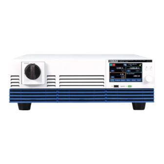
Bidirectional DC Power Supply
PXB Series
PXB20K-500
PXB20K-1000
PXB20K-1500
Part No. IB036161
Mar 2023
Contents 5
Component Names 8
Preparation 11
Basic Operation 22
Protection Functions 48
Advanced Functions 61
Memory Function 90
Sequence Function 100
External Control 122
System Settings 144
Maintenance 163
Specifications 169
Appendix 182
Advertisement
Table of Contents


Need help?
Do you have a question about the PXB Series and is the answer not in the manual?
Questions and answers