Advertisement
Quick Links
—— Instruction Manual ——
6" Hangtime EZ Swing Up Pole System
For the following packages: PR98GHT, PR98GHTJR, PR98SHT,
PR98SXLHT, PR98UHT, PR98UHTJR, HT6060G, HT6060GS, HT6072G
Item
Qty
Description
A
1
Ground Anchor**
B
1
Pole
C
1
Lower Arm
D
2
Upper Arm
E
1
Crank
F
1
Height Gauge
G
1
Pointer
H
1
Pole Cap
I
1
1/2" X 6 1/2" Hex Bolt
J
1
1/2"-13 Deformed Lock Nut
K
1
3/4" X 7" Hex Bolt
L
2
3/4" Hex Nut
M
2
3/4" Flat Washer
N
2
5/8" X 11" Hex Bolt
O
3
5/8" X 12" Hex Bolt
P
6
5/8" Lock Nut
Inspect all contents prior to installation. Report any missing parts to dealer immediately
Read all instructions before proceeding.
•
Improper installation, maintenance or use may cause product failure and serious personal injury.
•
Two or three people in good physical condition and capable of lifting at least 90-100lbs each are
1. Remove the plugs from the bolt holes in the Ground
Anchor (A) and inspect the threads to make sure they
are in good condition. Re-install the plugs, they keep
concrete and debris from getting into the bolt holes
during installation.
2. Determine the footing location. When the Rim (CC) is
at 10' height there is approximately 48" of safe play
area. Make sure that when installed the edge of the
Ground Anchor (A) is a minimum of 6" away from the
playing surface. Contact your local utility location
provider to avoid dangerous or inconvenient contact
with buried utilities. The footing should be 14"-18" in
diameter and 48"-50" deep. See Figures 1 & 2.
Date: 4/1/2020
Rev: 1
P A R T S L I S T
**Packaged Separately
Warning!
recommended for safe installation and assembly.
B.A.
N.J.C.
File: \ publisher\Hangtime\Hangtime Pole System
Item
Qty
Description
Q
1
5/8" X 5" Hex Bolt
R
4
5/8" X 1 1/2" Hex Bolt
S
4
5/8" Lock Washer
T
1
3/4" X 2" Hex Bolt
U
1
1/4" X 3" Hex Bolt
V
3
1/4" X 2 1/2" Hex Bolt
W
5
1/4" Hex Nut
X
1
Backboard** (see table on page 4)
Y
1
Backboard H-Frame** (see table on page 4)
Z
8
5/16" X 1" Machine Screw
AA
8
5/16" Lock Washer
BB
8
5/16" Hex Nut
CC
1
BA32 Rim** (BA39U optional)
DD
1
Pole Pad** (If applicable)
EE
1
Backboard Padding** (If applicable)
.
1
Customer Service
(800) 247-7668
Figure 1
Ref#: 920444
Advertisement

Related Manuals for Bison PR98GHT


Summary of Contents for Bison PR98GHT
- Page 1 —— Instruction Manual —— 6” Hangtime EZ Swing Up Pole System For the following packages: PR98GHT, PR98GHTJR, PR98SHT, Customer Service PR98SXLHT, PR98UHT, PR98UHTJR, HT6060G, HT6060GS, HT6072G (800) 247-7668 P A R T S L I S T **Packaged Separately Item...
- Page 2 Figure 2 3. Before pouring the concrete, make sure you have the required tools available including: a level, a broomstick or similar pole to vibrate the concrete, and a tape measure to correctly position the Ground Anchor (A). 4. Mix concrete per manufacturers instructions. Begin adding concrete into the hole until the concrete is approximately 28”-30”...
- Page 3 Figure 4 6. Remove the plugs from the threaded holes in the Ground Anchor (A). Unpack the Pole (B) and Crank (E). Align the hinge tabs on the Pole (B) with the hinge tube on the Ground Anchor (A). Insert the 1/2” X 6 1/2” Hex Bolt (I) through the hinge tabs.
- Page 4 5/8” X 11” Hex Bolt (N) and 5/8” Lock Nut (P). Tighten hardware then back off 1/2 turn. This is a pivot point, do not over tighten. See Figure 9. Figure 8 Package Backboard Required H-Frame HT6072G & BA42GHT HT6HFRAME2 PR98GHT PR98UHT BA42UHT HT6HFRAME2 HT6060G HT5HFRAME2 BA487 HT6060GSM BA487SM HT5HFRAME2...
- Page 5 HT6HFRAME2 For the following packages: HT6072G, PR98GHT, PR98UHT 1. Use the 5/16" X 1" Machine Screws (Z), 5/16" Lock Washers (AA) and 5/16" Hex Nuts (BB) to install Backboard H-Frame (Y) to Backboard (X). See Figure 11. 2. Once Backboard (X) is assembled refer to instruction 12 to complete system assembly.
- Page 6 Figure 12 12. Lift the assembled Backboard (X) and H-Frame (Y) up and align it with the bolt holes in the Lower Arm (C). Using a 5/8” X 12” Hex Bolt (O) and 5/8” Lock Nut (P) attach the Backboard (X) to the Lower Arm (C).
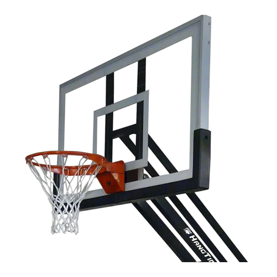
- Page 7 13. Install the Rim (CC) using the hardware and instructions provided with the Rim (CC). Install Net. 14. Install Pole Cap (H) on to the top of the Pole (B). See Figure 14. 15. Locate the four 5/8” X 1 1/2” Hex Bolts (R) and 5/8”...
- Page 8 Figure 16 17. Attach Height Gauge (F) to the Lower Arm (C) with a 1/4” X 2 1/2” Hex Bolt (V) and 1/4”Hex Nut (W) in the back mounting hole. Slide the Pointer (G) onto a 1/4”-20 X 3”Hex Bolt (U) then install one 1/4”...