Table of Contents
Advertisement
Quick Links
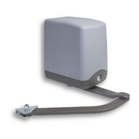
MAIN CHARACTERISTICS
Motor
Kind of limit switch
Tension of operation
Absorbed current
Absorbed power
Force
Opening time
Opening of the leaf
Max length of the leaf
Temporary service
AK-224 (incorporated control unit)
encoder on both motors
24Vdc
5A max
120W max
1200N
11.5s
90° - 100°
2m
80%
Tension for commands
Flashing light
Working time
Automatic closing time
Forewarn
Temperature of exercise
Protection grade
24Vdc 400mA max
25W 24Vdc
0-120s
0-120s
1.5s
-20°C - +70°C
IP56
1
Advertisement
Table of Contents

Subscribe to Our Youtube Channel
Related Manuals for B&R AK-224


Summary of Contents for B&R AK-224
- Page 1 MAIN CHARACTERISTICS Motor AK-224 (incorporated control unit) Tension for commands 24Vdc 400mA max Kind of limit switch encoder on both motors Flashing light 25W 24Vdc Tension of operation 24Vdc Working time 0-120s Absorbed current 5A max Automatic closing time 0-120s...
- Page 2 IMPORTANT WARNINGS! WARNING! FOR THE SAFETY OF PERSONS IT’S IMPORTANT Control board must be connected to feeding line by an Omni-polar TO FOLLOW THIS INSTRUCTIONS! switch, with opening distance between contacts not lower then 3mm. Such device must be protected from accidentally reactiva- KEEP CAREFULLY THIS INSTRUCTIONS! tion (installation on a lockable box).
- Page 3 Before proceeding with the installation we suggest to go through the followings checks and operations, beside verifying that the structure is comply- ing to the norms in force. In particular: • Check that the wall and/or column are in good conditions, otherwise it will be necessary to reinforce fixing points. •...
- Page 4 MOTOR’S MAINTENANCE DANGER: for any kind of maintenance, remove always the feeding. The motoreducer is supplied by a permanent grease lu- brication, therefore it doesn’t need any maintenances. Cables, springs and supports don’t need for periodic maintenance. In case of failure the system must be not used and professional stuff need to be called. CONTROL UNIT TABLE 1.
- Page 5 ELECTRICAL CONNECTIONS To guarantee the safety of operator and to prevent damages to components, while caring out the connections or inserting the radio receiver, the control unit must be disconnected from electric feeding. For feeding cables, motors lines, lines for blinker/ courtesy light, electric lock use a cable with appropriate section to the length of the connection (min 1,5mmq).
- Page 6 CONNECTION OF MOTORS ENCODER POSITIVE feeding of encoders are connected to clamp N.20 ENC+. NEGATIVE feeding of encoders are connected to clamp N.23 ENCIl. Signal of encoder relative to motor M1 to clamp N. 21 ENC1. Signal of encoder relative to motor M2 to clamp N. 22 ENC2. ELECTRONIC CLUTCH It’s a very important device for emergency, Its calibration stay constant in the time without being subject to usuries like in an usual mechanical clutch.
- Page 7 CONNNECTION CLAMPS FEEDINGS CN1 Connection clamps feedings CN1 The CN1 is dedicated to the connection of the control unit feeding: Clamp 1 VAC and clamp 2 VAC. To connect the 2 cables coming from the transformer where we could measure 22 Vac. Are protected by fuse F1 10A delayed.
- Page 8 DISPOSAL This product is composed of various components which may in turn contain pollutants. Do not dispose in the environment! Find out about the method for recycling or disposing of the product in compliance with current local laws. NOTES PROGET srl Via Europa, 3 31047 Ponte di Piave (TV) - ITALY tel.+39 (0)422 / 857377 fax +39 (0)422 / 857367...
Need help?
Do you have a question about the AK-224 and is the answer not in the manual?
Questions and answers