Table of Contents
Advertisement
Quick Links
ETAL210.1050-1
User's manual
Version: 1.00 (April 2020)
Order no.: User's manual
Translation of the original documentation
B&R reserves the right to make changes to the content without prior notice. B&R assumes no liability for typo-
graphical errors or for any other information in this document as far as legally possible. Liability claims against B&R
regarding the content of delivery and documentation of third-party components used in the product are excluded
in any case. The user is responsible for compliance with all relevant and professionally pertinent safety measures
as well as the intended use. B&R points out that the software and hardware designations and brand names of the
respective companies are subject to the legal protection regulations of intellectual property law.
ETAL210.1050-1 user's manual V1.00
1
Advertisement
Table of Contents

Subscribe to Our Youtube Channel
Related Manuals for B&R ETAL210.1050-1


Summary of Contents for B&R ETAL210.1050-1
- Page 1 The user is responsible for compliance with all relevant and professionally pertinent safety measures as well as the intended use. B&R points out that the software and hardware designations and brand names of the respective companies are subject to the legal protection regulations of intellectual property law. ETAL210.1050-1 user's manual V1.00...
-
Page 2: Table Of Contents
2 Repairing B&R products..........................15 Chapter 8 Accessories....................16 1 Required accessories............................16 2 Optional accessories............................19 Chapter 9 International and national certifications..........25 1 Directives and declarations..........................25 Chapter 10 Environmentally friendly disposal............26 1 Separation of materials............................26 ETAL210.1050-1 user's manual V1.00... -
Page 3: Chapter 1 Introduction
DIN ISO 2768 medium Up to 6 mm ±0.1 mm Over 6 to 30 mm ±0.2 mm Over 30 to 120 mm ±0.3 mm Over 120 to 400 mm ±0.5 mm Over 400 to 1000 mm ±0.8 mm ETAL210.1050-1 user's manual V1.00... -
Page 4: Chapter 2 Intended Use
Electronic devices are generally not failsafe. If the programmable logic controller, operating or control device or uninterruptible power supply fails, the user is responsible for ensuring that connected devices (such as motors) are brought to a safe state. ETAL210.1050-1 user's manual V1.00... -
Page 5: Transport And Storage
Internet, if necessary. The following measures and security solutions are suitable for this purpose: • Segmentation of the network (e.g. separation of the IT and OT networks) • Firewalls for the secure connection of network segments ETAL210.1050-1 user's manual V1.00... - Page 6 • Notable system modifications such as configuration changes • Deployment of updates or patches for third-party software (non-B&R software) • Hardware replacement These tests should ensure that implemented security measures remain effective and that systems behave as expected. ETAL210.1050-1 user's manual V1.00...
-
Page 7: Chapter 3 Safety Notices
• The operator is obliged to clearly define and manage responsibilities for installation, operation, fault cor- rection, maintenance and cleaning. • The operator is obliged to ensure that responsible personnel have read and understood this user's manual. ETAL210.1050-1 user's manual V1.00... -
Page 8: Chapter 4 System Characteristics
Chapter 4 • System characteristics 1 General information System ETAL210.1050-1 offers you a wide range of options from entry-level programming to more complex pro- gramming processes and even includes HMI. With other products from the ETA light system portfolio, the range of functions can be easily adapted and expanded to meet training needs. - Page 9 System characteristics • Content of delivery X20CP1586 5CFCRD.0512-06 ETAL100.3200-12 For details and additional technical data, see the data sheets for the individual products. ETAL210.1050-1 user's manual V1.00...
-
Page 10: Chapter 5 Technical Data
1.4 kg Brief overview Content of delivery This product contains the following materials: ETAL100.0200-1 X20CP1586 5CFCRD.0512-06 ETAL100.3200-12 For details and additional technical data, see the data sheets for the individual products. Table 2: ETAL210.1050-1 - Technical data ETAL210.1050-1 user's manual V1.00... -
Page 11: Chapter 6 Commissioning
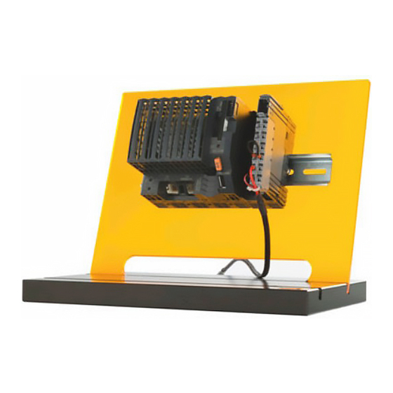
For additional information, see the documentation of the product used. 2 Construction The product must be placed on a flat, stable surface with the module rack available in the accessories. Figure 1: The figure does not have to correspond to the actual product! ETAL210.1050-1 user's manual V1.00... -
Page 12: Safety
Check the following elements for visible defects (cracks, loose screw connections and the like) before commis- sioning. • Electrical connections • Safety devices and covers • Mechanical components Advice: Commissioning is only permitted to be carried out under the supervision of a specialist with the cor- responding qualifications! ETAL210.1050-1 user's manual V1.00... -
Page 13: Power Supply
Depending on the format selected for project transfer, the application data is stored in basic or mirrored format. During training, basic data storage is usually sufficient. ETAL210.1050-1 user's manual V1.00... -
Page 14: Chapter 7 Maintenance
1. Perform electrostatic discharge at the top-hat rail or at the ground connection (do not reach into the power supply unit!) 2. Remove the cover for the lithium battery. Do this by sliding it down and away from the CPU. ETAL210.1050-1 user's manual V1.00... -
Page 15: Repairing B&R Products
The housing of B&R products is only permitted to be opened if this is necessary for assembly, instal- lation, maintenance or repair work as required in the user documentation. Handling repairs and complaints The B&R Material Return Portal is available on the B&R website (www.br-automation.com) for processing repair or complaint cases. ETAL210.1050-1 user's manual V1.00... -
Page 16: Chapter 8 Accessories
1.1.3 Technical data Model number 0TP370.76 Cable construction Wire cross section 3x 0.75 mm² Type H05-VV-F3G Supply lines Permissible operating voltage 250 VAC Outer jacket Color Black Mechanical properties Length Table 4: 0TP370.76 - Technical data ETAL210.1050-1 user's manual V1.00... - Page 17 24 VDC voltage output Voltage range 24 VDC Output current 2.5 A Connector Type P1J 5.5 x 2.1 Mechanical properties Dimensions Width 50 mm Height 31.5 mm Depth 125 mm Weight 310 g Table 6: 0TP650.07 - Technical data ETAL210.1050-1 user's manual V1.00...
- Page 18 ETA light systems, groove distance: 8 cm. Table 7: ETAL100.0000-2 - Order data 1.3.3 Technical data Model number ETAL100.0000-2 Mechanical properties Dimensions Width 300 mm Height 230 mm Depth 6 mm Table 8: ETAL100.0000-2 - Technical data ETAL210.1050-1 user's manual V1.00...
-
Page 19: Optional Accessories
2.1 ETAL120.1050-1 2.1.1 General information ETAL210.1050-1 offers a wide range of possibilities. In order to implement exercises with sensors and actuators, the ETA light system can be extended by this product. Simple exercises can be implemented, such as latching or level monitoring, as can more complex tasks such as traffic lights, running lights and the like. - Page 20 Accessories • Optional accessories Model number ETAL120.1050-1 Mechanical properties Dimensions Width 300 mm Height 90 mm Depth 70 mm Table 10: ETAL120.1050-1 - Technical data ETAL210.1050-1 user's manual V1.00...
- Page 21 INT / 0 - 10 VDC 2.1.5 Compatibility This product is intended to be used with the ETAL210.1050-1. Using this product in combination with other X20 components is possible in principle, but requires a thorough examination of whether the I/O configuration matches the wiring of this product.
- Page 22 Low voltage female connector 5.5 mm / 2.1 mm (0TP650.07) Cable construction Wire cross section On input 20 AWG / On output 24 AWG Properties Nickel-plated contacts Outer jacket Material Mechanical properties Length 450 mm Table 12: ETAL100.1Y05-0 - Technical data ETAL210.1050-1 user's manual V1.00...
- Page 23 2.3 POWERLINK cables Short description Length POWERLINK cables 0.5 m X20CA0E61.00050 X20CA0E61.00100 1.5 m X20CA0E61.00150 X20CA0E61.00200 Length Tolerances for cable lengths X20CA0E61.xxxxx 0.2 to 0.5 m +0.01 m 1 to 5 m +0.04 m 2.4 Technical data ETAL210.1050-1 user's manual V1.00...
- Page 24 Accessories • Optional accessories 2.5 X20CA0E61.xxxxx Dimensions Length xxxx Pinout Male RJ45 connector Male RJ45 connector Shield White/Orange Orange White/Green Blue White/Blue Green White/Brown Brown ETAL210.1050-1 user's manual V1.00...
-
Page 25: Chapter 9 International And National Certifications
RoHS directive 2011/65/EU (RoHS II) All devices satisfy the protection requirements of this directive. Applicable standard from this directive: EN 50581 Technical documentation for the assessment of electrical and electronic products with respect to the restriction of haz- ardous substances ETAL210.1050-1 user's manual V1.00... -
Page 26: Chapter 10 Environmentally Friendly Disposal
Programmable logic controllers Electronics recycling Operating and monitoring devices Uninterruptible power supplies Batteries and rechargeable batteries Cables Paper/Cardboard packaging Paper/Cardboard recycling Plastic packaging material Plastic recycling Disposal must be carried out in accordance with applicable legal regulations. ETAL210.1050-1 user's manual V1.00... - Page 27 Publishing information ETAL210.1050-1 user's manual V1.00...
- Page 28 Publishing information Publishing information B&R Industrial Automation GmbH B&R Strasse 1 5142 Eggelsberg Austria Telephone: +43 7748 6586-0 Fax: +43 7748 6586-26 office@br-automation.com ETAL210.1050-1 user's manual V1.00...
Need help?
Do you have a question about the ETAL210.1050-1 and is the answer not in the manual?
Questions and answers