
Related Manuals for RITE-HITE Mechanical Dock Leveler Hydraulic Conversion


Summary of Contents for RITE-HITE Mechanical Dock Leveler Hydraulic Conversion
- Page 1 Mechanical Dock Leveler Hydraulic Conversion A F T E R M A R K E T C O R P O R A T I O N Installation & Owner’s Manual Rite-Hite Print Shop Pub. 1147- Rev. 7 SEPTEMBER 2004...
-
Page 2: Table Of Contents
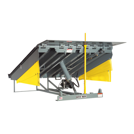
INTRODUCTION RITE-HITE ® Mechanical Dock Leveler Hydraulic Conversion provides a practical alternative to ’S applications where “basic automatic operating characteristics” are desired. The unit is operated by a single, remote pushbutton control box. An electro-hydraulic power unit delivers hydraulic oil to heavy duty cylinders for platform and lip operation. -
Page 3: Safety Warnings
RITE-HITE Corporation does not recommend any particular lockout device, but recommends the utilization of an ® OSHA approved device (refer to OSHA regulation 1910.147). RITE-HITE Corporation also recommends the review ® and implementation of an entire safety program for the Control of Hazardous Energy (Lockout/Tagout). These regulations are available through OSHA publication 3120. -
Page 4: Definition Of Features On The Hydraulic Conversion
Mechanical Dock Leveler Hydraulic Conversion DEFINITIONS OF FEATURES Rear Ramp Lip Hinge Pin Platform Lip Bracket Platform Hinge Pin Cylinder Lug Ramp Clevis Lip Lug Subframe Lip Keepers Front Bracket Pit Rear Floor MECHANICAL COMPONENTS Power Unit Front Rear ELECTRICAL COMPONENTS... - Page 5 SAFE-T-STRUT AND BASE dock position when not in use. ® The hydraulic conversion is shipped with the RITE-HITE SAFE-T-STRUT . This SAFE-T-STRUT is inserted through a pre-drilled hole in the lip and then secured by...
-
Page 6: Preparation Instructions
Mechanical Dock Leveler Hydraulic Conversion PREPARATION INSTRUCTIONS MOVABLE REAR HINGES LEVELERS PROTRUDING FROM DOCK If a leveler that is to be converted has a rear hinge that can slide or move verti- Levelers that protrude from the loading dock cally, this hinge will need to be locked in a may be converted, but the front sub-frame position that does not allow sliding movement. -
Page 7: Installation Instructions
Mechanical Dock Leveler Hydraulic Conversion INSTALLATION INSTRUCTIONS CAUTION CAUTION Be sure to follow these Caution notes when installing your Mechanical Dock Leveler Hydraulic C o v e r c y l i n d e r w i t h f l a m e r e t a r d a n t Conversion Kit c o v e r i n g b e f o r e w e l d i n g . -
Page 8: Electrical Installation Detail
Mechanical Dock Leveler Hydraulic Conversion ELECTRICAL INSTALLATION DETAILS FIGURE 2 Pub. 1147 - Rev. 7 SEPTEMBER 2004... -
Page 9: Hydraulic Conversion Installation
Mechanical Dock Leveler Hydraulic Conversion INSTALLATION DETAILS HYDRAULIC CONVERSION CAUTION INSTALLATION INSTRUCTIONS WARNING Insure the structural integrity of the leveler. Make sure the leveler will have at least five more years of useful life L O C K O U T / T A G O U T P R O C E D U R E S after the conversion is complete. - Page 10 Mechanical Dock Leveler Hydraulic Conversion WARNING CAUTION I n s u r e t h a t t h e c o n c r e t e i s a t W E L D I N G P R O C E D U R E S : l e a s t 4 ”...
- Page 11 Mechanical Dock Leveler Hydraulic Conversion WARNING I M P O R TANT S e l e c t t h e m e t h o d f o r i n s t a l l i n g t h e...
- Page 12 Mechanical Dock Leveler Hydraulic Conversion INSTRUCTIONS FOR THE POST ONLY STRUT BASE (Type I) Perform the work in this order: 1. Locate the strut base within 12" of the centerline of the leveler so that it does not interfere with the board operation.
- Page 13 Mechanical Dock Leveler Hydraulic Conversion INSTRUCTIONS FOR THE POST WITH EXTENSION STRUT BASE (Type II) Perform the work in this order: 1. Measure the height of the front sub-frame. 2. Slide the base into the non-chamfered side of the base extension. Measure the distance from the shoulder of the base to the bottom of the base extension.
- Page 14 Mechanical Dock Leveler Hydraulic Conversion INSTRUCTIONS FOR STRUT BASE UTILIZING BASE AND BASE ANGLE (Type III) Perform the work in this order: 1. Center the Safe-T-Strut base on the angle and align the chamfer on the base with the radius on the front of the angle.
-
Page 15: Installation
Mechanical Dock Leveler Hydraulic Conversion LIP INSTRUCTIONS 1. Locate and drill 1-1/4" dia. Hole in the leveler lip in line with the base positioning. It is usually best to put the hole close to the lip hinge so the strut is nearly vertical once installed. See Figure 8. On levelers with a spool outside diameter of 2"... - Page 16 Mechanical Dock Leveler Hydraulic Conversion 12.00 REF. Chain Assy. FIGURE 10 (CHAIN INSTALLATION) FIGURE 11 (DECAL INSTALLATION) Insure the bracket is square to the leveler deck so CUT AWAY ALL MECHANICAL HARDWARE the hydraulic cylinder stays on the center line of the 1.
- Page 17 Mechanical Dock Leveler Hydraulic Conversion member must be added so the bridge is not Draw a line on the pit floor parallel to the hinge at weakened. The recommended bridge opening for this position. This dimension is critical to make...
- Page 18 Mechanical Dock Leveler Hydraulic Conversion 3. Turn adapter onto 90 elbow of ramp cylinder. Fasten securely. 4. Install velocity fuse into adapter of ramp cylinder. Fasten securely. 5. Install hoses between the pump and the ramp and lip cylinders. The small hose should be connected to the lip cylinder and the larger hose should get fastened the velocity fuse on the ramp cylinder.
- Page 19 Mechanical Dock Leveler Hydraulic Conversion ELECTRICAL WIRING PUMP ADJUSTMENTS 1. Connect electrical wiring per Figures 18-27. Be 1. Run leveler and adjust properly sure to use the correct wiring diagram for the power a. Adjust shuttle valve so that leveler platform provided and the pump assembly ordered.
- Page 20 Mechanical Dock Leveler Hydraulic Conversion QUICK CLEAN FRAME MODIFICATIONS FIGURE 14 Pub. 1147 - Rev. 7 SEPTEMBER 2004...
- Page 21 Mechanical Dock Leveler Hydraulic Conversion FIGURE 15 Pub. 1147 - Rev. 7 SEPTEMBER 2004...
- Page 22 Mechanical Dock Leveler Hydraulic Conversion POSSIBLE ARTD RECYCLE loosen the bottom collar, reposition and tighten the collar. See Figure 17A-B. Re-test the unit. Tighten all PROBLEMS AND ADJUSTMENT shaft collars to 35 in-lbs. 1. If the unit fails to raise high enough to enable the lip to fall into the lip supports, the Restrictor Limit Switch needs to be adjusted.
- Page 23 Mechanical Dock Leveler Hydraulic Conversion Front Header Collar 1/16” Between Center of Switch and Edge of Cam Block Limit Switch Block Bottom Collar FIGURE 17B - ARTD ADJUSTMENT Pub. 1147 - Rev. 7 SEPTEMBER 2004...
-
Page 24: Electrical Schematics
Mechanical Dock Leveler Hydraulic Conversion WIRING DIAGRAMS AND SCHEMATICS TYPE 1 CONTROLS See Electrical Motor – 3/4 HP 2850/3450 RPM Installation Details Below 60 / 75 C Copper 120/240V 1 Ph. 50/60 Hz. Pushbutton Intermittent Duty Wire/100 Ft. Of Run... - Page 25 Mechanical Dock Leveler Hydraulic Conversion Branch Circuit Disconnect Motor Motor – 1 HP Control Box Junction Box @3450 RPM, 208/240V, 1 O/L 3 Ph., 50/60 Hz. 2 O/L 3 O/L Set @ 208/240V 4.4 Amp H1 H3 Motor Lead Connections Use Min.
- Page 26 Mechanical Dock Leveler Hydraulic Conversion Branch Circuit Disconnect Motor Motor – 1 HP Control Box Junction Box @3450 RPM, 380V, 1 O/L 3 Ph., 50 Hz. 2 O/L 3 O/L Set @ 2.6 Amp 380V Motor Lead Connections Use Min. #12 Gage...
- Page 27 Mechanical Dock Leveler Hydraulic Conversion Branch Circuit Disconnect Motor Motor – 1 HP Control Box Junction Box @3450 RPM, 480V, 1 O/L 3 Ph., 50/60 Hz. 2 O/L 3 O/L Set @ 2.2 Amp 480V H1 H3 Motor Lead Connections Use Min.
- Page 28 Mechanical Dock Leveler Hydraulic Conversion Branch Circuit Disconnect Motor Motor – 1 HP Control Box Junction Box @3450 RPM, 575V, 1 O/L 3 Ph., 50/60 Hz. 2 O/L 3 O/L Set @ 1.9 Amp 575V Motor Lead Connections Use Min. #12 Gage...
- Page 29 Mechanical Dock Leveler Hydraulic Conversion NORMAL VOLTAGE AND AMPERAGE Motors Incoming Line Voltage Starting Voltage Starting Amps Minimum Running (from electrical sources) Running Voltage Amps 120 Volt - 1 Phase 7 to 14 208 Volt - 1 Phase 4 to 7 230 Volt - 3 Phase 3.8 to 5.5...
-
Page 30: Operating Instructions
Mechanical Dock Leveler Hydraulic Conversion OPERATING INSTRUCTIONS NORMAL OPERATION WITHOUT WARNING ARTD I M P O R TANT Read and obey these instructions to prevent personal injury. • DO NOT operate leveler with anyone • I f a n y l o a d i s o n t h e l e v e l e r standing on, or in front of lip. - Page 31 Mechanical Dock Leveler Hydraulic Conversion NORMAL OPERATION WITH OPTIONAL AUTOMATIC RETURN TO DOCK (ARTD) WARNING • I f a n y l o a d i s o n t h e l e v e l e r p l a t f o r m , D O N O T o p e r a t e .
- Page 32 Mechanical Dock Leveler Hydraulic Conversion BELOW DOCK END LOADS AND 5. If the lip is on the truck/trailer and the truck pulls out, the leveler will move to its lowest position and the lip END LOADING WITH OPTIONAL will begin to lower. As the lip drops toward the...
-
Page 33: Maintenance
Mechanical Dock Leveler Hydraulic Conversion MAINTENANCE LUBRICATION 3. Once below dock loading or end loading is complete, push and hold the RAISE button on the 1. Barricade the leveler off to all forms of traffic. control box until the leveler is 6” to 10” above dock level. - Page 34 Mechanical Dock Leveler Hydraulic Conversion SHUTTLE VALUE ADJUSTMENT Viewed From (CONTROLS LEVELER DESCENT) System Tank End Relief Valve Sequence Valve DANGER Shuttle Valve Body • O-Rings D o n o t o p e r a t e l e v e l e r w i t h a n y o n e s t a n d i n g o n o r i n f r o n t o f t h e l i p .
- Page 35 Mechanical Dock Leveler Hydraulic Conversion SEQUENCE VALVE ADJUSTMENT 6. Re-test the unit several times to verify the setting. 7. If the lip begins to extend at any time before the (CONTROLS LIP EXTENSION) platform has fully raised, the Sequence Valve setting is too low.
-
Page 36: Hydraulic Schematic
Mechanical Dock Leveler Hydraulic Conversion HYDRAULIC SCHEMATIC Power Unit Assembly Motor - Velocity Fuse Suctin 3450 RPM Filter RAMP Port Ramp Cylinder : Check (6' And 8') Pump Valve 3-1/2" x 12" S.A. (10') Adjustable Pilot Adjustable 3-1/2" x 16" S.A. -
Page 37: Optional Equipment
Mechanical Dock Leveler Hydraulic Conversion OPTIONAL EQUIPMENT - DOOR INTERLOCK FIGURE 38 FIGURE 39 Pub. 1147 - Rev. 7 SEPTEMBER 2004... -
Page 38: Troubleshooting
Mechanical Dock Leveler Hydraulic Conversion TROUBLESHOOTING This equipment is shipped from the factory I M P O R TANT fully tested and totally operative. The vast majority of operating problems are caused by UNNECESSARY ADJUSTMENT BY Before attempting any troubleshooting UNTRAINED PERSONNEL. - Page 39 Mechanical Dock Leveler Hydraulic Conversion TROUBLESHOOTING Problem Probable Cause Remedy 1. Platform does not raise (motor not a. Power has been disconnected. a. Verify that power has not been running) disconnected. Verify that disconnect circuit breakers or fuses are not tripped.
- Page 40 Mechanical Dock Leveler Hydraulic Conversion Problem Probable Cause Remedy 2. Platform does not raise (motor running) c. Hydraulic fluid level is low. c.Check oil level in tank. -Continued. Refill if there is less than 3-1/2" of oil in the tank when the unit is held open with the SAFE-T-STRUT™.
- Page 41 Mechanical Dock Leveler Hydraulic Conversion Problem Probable Cause Remedy 4. Lip extends slowly and/or does not c. Hydraulic fluid level is low. c.Check oil level in tank. fully extend. -Continued Refill if there is less than 3-1/2" of oil in the tank when the unit is held open with the SAFE-T-STRUT™.
- Page 42 Mechanical Dock Leveler Hydraulic Conversion Problem Probable Cause Remedy Platform does not lower. a. Hydraulic fluid level is low. a.Check oil level in tank. Refill if there is less than 3-1/2" of oil in the tank when the unit is held open with the SAFE-T-STRUT™.
- Page 43 Mechanical Dock Leveler Hydraulic Conversion Problem Probable Cause Remedy 10. Lip does not store or store properly e. Valve failures on power unit endhead. e. Inspect, test and replace the pilot to in lip supports. – Continued close check valve if necessary.
- Page 44 Mechanical Dock Leveler Hydraulic Conversion Problem Probable Cause Remedy 13. Fuse or circuit breaker frequently a. Undersized fuse or circuit breaker. a. Verify 20 Amp for 120VAC and 15 Amp trips. for 240VAC. b. Low voltage. b. Verify ±10% nominal voltage while unit is running.
- Page 45 Mechanical Dock Leveler Hydraulic Conversion HYDRAULIC PLUMBING Power Unit Left Side View Power Unit Right Side View Item Quantity Description 5' Long 8' Long 6' Long 10' Long Power Unit – Single Phase 113248 113248 113248 113248 Power Unit – 240/380/480 Volt 3 Phase...
- Page 46 Mechanical Dock Leveler Hydraulic Conversion Pub. 1147 - Rev. 7 SEPTEMBER 2004...
- Page 47 Mechanical Dock Leveler Hydraulic Conversion OPTIONAL ARTD ASSEMBLY Item# Quantity Description Part# ARTD Assembly 106026 Shoulder Bolt, 3/8 dia. x .50 104394 Actuator Guide Rod 100132 Clevis Pin, Lip Cyl, Rod End 102311 Cotter Pin, 1/8 x 1-1/2 51903 Spacer Tube 100131 U-Bolt, 2"...
-
Page 48: Replacement Parts
Wire, #12 AWG, Black, 60°/75° Wire, #12 AWG, Black, 60° x 4 Lg. 17689 Washer, External Tooth Lock, #8 17803 CB Decal Cover 100589 * For part numbers of any control box style other than the standard, please contact your local representative or RITE-HITE ® Pub. 1147 - Rev. 7 SEPTEMBER 2004... - Page 49 Terminal Block Assembly (120V) 114367 & 114374 Terminal Block Assembly (240V) 114367 & 114368 * For part numbers of any control box style other than the standard, please contact your local representative or RITE-HITE ® Pub. 1147 - Rev. 7 SEPTEMBER 2004...
- Page 50 102647 102646 102648 Drawing, Electric Schematic with ARTD 102641 102643 102642 102644 * For part numbers of any control box style other than the standard, please contact your local representative or RITE-HITE ® Pub. 1147 - Rev. 7 SEPTEMBER 2004...
- Page 51 115.479 115.479 115.479 Drawing, Electric Schematic with options 179.106 179.121 179.105 179.120 * For part numbers of any control box style other than the standard, please contact your local representative or RITE-HITE ® Pub. 1147 - Rev. 7 SEPTEMBER 2004...
- Page 52 Mechanical Dock Leveler Hydraulic Conversion Pub. 1147 - Rev. 7 SEPTEMBER 2004...
- Page 53 Mechanical Dock Leveler Hydraulic Conversion STANDARD SAFE-T-STRUT Item Part Description Quantity 0103735 Universal Safe-T-Strut Kit 103967 Safe-T-Strut - 63" long 51100 Anchor Loop, .25" wire dia. 16182 Chain assembly 59387 Base, 4.25", Safe-T-Strut 103349 Extension, Base 103495 Competitive Base support angle...
- Page 54 Mechanical Dock Leveler Hydraulic Conversion MECHANICAL PARTS Pub. 1147 - Rev. 7 SEPTEMBER 2004...
- Page 55 Mechanical Dock Leveler Hydraulic Conversion MECHANICAL PARTS Item# Quantity Description Part# Toe Guard, 6’ Leveler, RH 1725 Toe Guard, 6’ Leveler RH 1724 Toe Guard, 8’ Leveler, RH 1707 Toe Guard, 8’ Leveler, LH 1708 Lip Keepers, Hydraulic 2175 Toe Guard 10’ Leveler RH...
-
Page 56: Warranty
Corporation warranties, if any, must be specified by RITE-HITE Corporation in writing. In the event of any defects covered by this warranty, RITE-HITE Corporation will remedy such defects by repairing or replacing any defective equipment or parts, bearing all of the costs for parts, labor, and transportation. This shall be the exclusive remedy for all claims whether based on contract negligence or strict liability.
Need help?
Do you have a question about the Mechanical Dock Leveler Hydraulic Conversion and is the answer not in the manual?
Questions and answers