Table of Contents
Advertisement
This Manual Covers Levelers Built After Serial Numbers:
ML Series: 04CD100001 and up HL Series: 04CD120001 and up
AL Series: 04CD130001 and up
PRINTED IN U.S.A.
COPYRIGHT 2004
By Rite-Hite
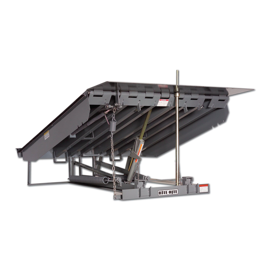
HL-900 Hydraulic
Dock Leveler
Dock Leveler
Owners Manual
ML-900 Mechanical
Dock Leveler
AL-900 Air Powered
Dock Leveler
MADE IN THE U.S.A.
Effective 4/1/04
PUBLICATION NO. 1185-R1
AUGUST 2004
Advertisement
Table of Contents
Troubleshooting

Related Manuals for RITE-HITE Genisys ML-900


Summary of Contents for RITE-HITE Genisys ML-900
- Page 1 Dock Leveler Owners Manual By Rite-Hite ML-900 Mechanical Dock Leveler HL-900 Hydraulic Dock Leveler AL-900 Air Powered Dock Leveler MADE IN THE U.S.A. Effective 4/1/04 This Manual Covers Levelers Built After Serial Numbers: ML Series: 04CD100001 and up HL Series: 04CD120001 and up AL Series: 04CD130001 and up PRINTED IN U.S.A.
- Page 2 Genisys Dock Leveler Owners Manual NOTES Pub. No. 1185-R1 - August 2004...
-
Page 3: Table Of Contents
ELECTRICAL SCHEMATICS - HL-900/AL-900 ...........25 NOTICE TO USER ® Your local RITE-HITE representative provides a Planned Maintenance Program (P.M.P.) which can be fitted to your ®... -
Page 4: Safety Warnings
RITE-HITE PRODUCTS CORPORATION does not recommend any particular lockout device, but recommends the utilization of an OSHA approved device (refer to OSHA regulation 1910.147). RITE-HITE PRODUCTS CORPORATION also recommends the review and implementation of an entire safety program for the Control of Hazardous Energy (Lockout/Tagout). - Page 5 • When leveler is not in use, always store it so that it is supported by the lip supports and that it is level with the surrounding dock floor. • If a malfunction does occur, always call your ® authorized RITE-HITE service representative immediately. Pub. No. 1185-R1 - August 2004...
- Page 6 ONTO BASE • If you are unable to install the Maintenance Figure 2 - Install Maintenance Support Support properly, contact your authorized ® RITE-HITE Service Representative or RITE- ® HITE Customer Service at 1-414-355-2600. Pub. No. 1185-R1 - August 2004...
-
Page 7: Owner Responsibility
As with any piece of machinery, dock equipment of the interface between dock and transport requires routine maintenance, lubrication, and vehicle. The owner should, therefore, train and adjustments. Your local RITE-HITE ® representative instruct operators in the safe use of dock... -
Page 8: Operation Instructions
Genisys Dock Leveler Owners Manual OPERATION INSTRUCTIONS MECHANICAL NOTE: BELOW DOCK LOADING OPERATION End loads at dock level and above can be handled 1. To service truck/trailers with beds lower than the with the leveler in its stored position. dock level, activate the leveler by pulling and holding the ramp control release chain until platform is at the Be sure the lip is in full contact with the truck/trailer highest position and the lip is fully extended. - Page 9 Genisys Dock Leveler Owners Manual OPERATION INSTRUCTIONS MECHANICAL CONT. Safety Leg Chain Figure 7 - Leveler Stored Figure 6 - End Load Operation STORING LEVELER BELOW DOCK END LOADING OPERATION 1. To store the leveler if platform is lower than dock level, jog the ramp control release chain until 1.
- Page 10 Genisys Dock Leveler Owners Manual OPERATION INSTRUCTIONS POWERED LEVELERS NOTE: BELOW DOCK LOADING OPERATION End loads at dock level and above can be handled 1. Activate the leveler by pushing and holding the with the leveler in its stored position. RAISE button until leveler is fully raised and lip is fully extended.
- Page 11 Genisys Dock Leveler Owners Manual OPERATION INSTRUCTIONS POWERED LEVELERS CONT. 2. When lip extends about 2 inches, release RAISE button. The leveler will lower to the below dock position with the lip positioned between the face of the loading dock and the truck/trailer bed. See figure 12.
-
Page 12: Maintenance Procedures
Genisys Dock Leveler Owners Manual MAINTENANCE PROCEDURES 8. Air powered leveler only: With the leveler supported by the maintenance strut, inspect the air tower and blower for damage. Replace if worn or damaged. Read and obey these instructions to prevent personal injury. - Page 13 Genisys Dock Leveler Owners Manual MAINTENANCE PROCEDURES OIL SAE 30 Weight Figure 15 - Mechanical Leveler Lubrication OIL SAE 30 Weight Figure 16 - Hydraulic Powered Leveler Lubrication Pub. No. 1185-R1 - August 2004...
- Page 14 Genisys Dock Leveler Owners Manual MAINTENANCE PROCEDURES OIL SAE 30 Weight Anti-Seize Figure 17 - Air Powered Leveler Lubrication Pub. No. 1185-R1 - August 2004...
- Page 15 Genisys Dock Leveler Owners Manual MECHANICAL LEVELER ADJUSTMENTS NEVER REMOVE adjustment nuts from main spring Make sure to position the maintenance support adjustment rod. Serious injury or death will occur. when making the lip assist spring adjustment. INSERT INTO CUP •...
- Page 16 2. Lip is partially extended. a. Platform did not raise fully. a. Adjust main springs. See adjustment procedures or replace damaged springs. Consult local representative or Rite-Hite. b. Lip assist spring out of b. Adjust lip assist spring. See adjustment. adjustment procedures.
- Page 17 Genisys Dock Leveler Owners Manual HYDRAULIC LEVELER ADJUSTMENTS HYDRAULIC POWERED LEVELER OPTIONAL ARTD: ADJUSTMENTS ARTD Limit Switch Cam NOTE: This limit switch senses the position of the lip during leveler automatic return to dock (ARTD) via the The adjustments listed below are factory averages, ARTD cam.
- Page 18 Genisys Dock Leveler Owners Manual HYDRAULIC LEVELER ADJUSTMENTS CONT. RAMP CYLINDER PORT PILOT TO LIP CYLINDER PORT CLOSE CHECK VALVE ADJUSTABLE ADJUSTABLE SEQUENCE SHUTTLE VALVE VALVE PILOT OPERATED CHECK VALVE ADJUSTABLE RELIEF VALVE Figure 20 - Power Unit End Head •...
- Page 19 Genisys Dock Leveler Owners Manual HYDRAULIC LEVELER ADJUSTMENTS CONT. SEQUENCE VALVE ADJUSTMENT (CONTROLS LIP EXTENSION) Note: • Check oil level before making any adjustments. 1. When the leveler is fully raised and the lip does not extend, the Sequence Valve is set too high. 2.
- Page 20 Genisys Dock Leveler Owners Manual HYDRAULIC POWERED LEVELER TROUBLESHOOTING Problem Probable Cause Solution 1. Platform does not raise a. Power has been disconnected. a. Verify that power has not been disconnected. Verify that disconnect circuit breaker or fuses are not tripped. b.
-
Page 21: Hydraulic Leveler - Hydraulic Schematic
Genisys Dock Leveler Owners Manual HYDRAULIC LEVELER - HYDRAULIC SCHEMATIC POWER UNIT ASSEMBLY VELOCITY FUSE FILTER MOTOR 6 GPM (6') OPTIONAL 3450 RPM 2.5 GPM (8') 2W N.O. VALVE MICRON "RAMP" FOR IFC PORT ANTI-CAVITATION PUMP CHECK 1.4 GPM VALVE @ 880 PSI ADJ SHUTTLE P.T.C. -
Page 22: Pub. No. 1185-R1 - August
Genisys Dock Leveler Owners Manual AIR POWERED LEVELER ADJUSTMENTS LIP LATCH BOLT ADJUSTMENT LIP LATCH BOLTS The lip latch bolt is factory adjusted prior to installa- LOCK NUTS tion. Over time however, if the lip does NOT latch when the leveler is fully raised and remain latched as the platform lowers, the lip latch bolt may need to be readjusted. - Page 23 Genisys Dock Leveler Owners Manual AIR POWERED LEVELER TROUBLESHOOTING Problem Probable Cause Solution 1. Platform does not raise a. Power has been disconnected. a. Verify that power has not been disconnected and that disconnect circuit breaker or fuses are not tripped. b.
- Page 24 Genisys Dock Leveler Owners Manual ELECTRICAL WIRING CHARTS Average Motor Loads (Amps) Hydraulic Leveler Levelers 3/4 hp 110-120/1 12.0 10.0 14.5 208-230/1 208-230/3 380-415/3 440-480/3 575-600/3 Minimum Wire Size Chart for Various Line Lengths and Line Loads Line Length (In Feet) 0-50 51-100 101-150 151-200 201-205 251-300 301-350 351-400 110-120/1 1300 watts Air Powered Levelers 110-120/1...
- Page 25 BE LOCATED WITHIN A 50 FT. RADIUS IF FUSED DISCONNECT IS MOTOR CONNECTIONS 110-120v. 1Ph. AND BE VISIBLE FROM THE CONTROL NOT PROVIDED BY RITE-HITE 110-120v. 1Ph. IF ROTATION IS WRONG PRODUCTS CORPORATION, BOX LOCATION. [REFERENCE LATEST IF ROTATION IS WRONG REVERSE T5 AND T8 LINES.
- Page 26 WITHIN A 50 FT. RADIUS AND BE VISIBLE FROM THE CONTROL BOX LOCATION. [REFERENCE LATEST (BY OTHERS) EDITION OF NEC, SECTION 430] IF FUSED DISCONNECT IS NOT PROVIDED BY RITE-HITE PRODUCTS CORPORATION, FUSED DISCONNECT MUST BE PROVIDED BY OTHERS AND MOTOR CONNECTIONS MOTOR CONNECTIONS INSTALLED PER LATEST EDITION OF 110-120v.
- Page 27 A BRANCH CIRCUIT DISCONNECT SHALL BE LOCATED (BY OTHERS) WITHIN A 50 FT. RADIUS AND BE VISIBLE FROM THE IF FUSED DISCONNECT IS NOT CONTROL BOX LOCATION. [REFERENCE LATEST PROVIDED BY RITE-HITE EDITION OF NEC, SECTION 430] MOTOR CONNECTIONS MOTOR CONNECTIONS PRODUCTS CORPORATION, 110-120v.
- Page 28 LOCATED WITHIN A 50 FT. (BY OTHERS) 208-240V 3PH. RADIUS AND BE VISIBLE IF FUSED DISCONNECT IS NOT FROM THE CONTROL BOX CONNECT T1, T2, T3 PROVIDED BY RITE-HITE LOCATION. [REFERENCE TO TERMINALS1, 2, 3. PRODUCTS CORPORATION, MOTOR MOTOR LATEST EDITION OF NEC,...
- Page 29 Genisys Dock Leveler Owners Manual ELECTRICAL SCHEMATIC - HYDRAULIC LEVELER CONT. MOTOR CONNECTIONS 440-480v. 3 PH. CONNECT T1, T2, T3 FROM CUSTOMER MAIN POWER & SAFETY PROTECTION DEVICE TO TERMINALS 1, 2, 3. IF ROTATION IS WRONG, 208-240v. 3PH. 60HZ. USE 6.0A DUAL ELEMENT TIME DELAY FUSES REVERSE ANY 2 LINES.
- Page 30 A BRANCH CIRCUIT DISCONNECT SHALL BE LOCATED WITHIN A 50 FT. RADIUS IF FUSED DISCONNECT IS AND BE VISIBLE FROM THE CONTROL NOT PROVIDED BY RITE-HITE BOX LOCATION. [REFERENCE LATEST PRODUCTS CORPORATION, EDITION OF NEC, SECTION 430] FUSED DISCONNECT MUST...
- Page 31 Genisys Dock Leveler Owners Manual ELECTRICAL SCHEMATICS - AIR LEVELER CONT. FROM CUSTOMER MAIN POWER & SAFETY PROTECTION 110-120v. 1PH. 60HZ. USE 15.0A DUAL ELEMENT TIME DELAY 208-240v. 1PH. 60HZ. USE 10.0A DUAL ELEMENT TIME DELAY 208-240v. 1PH. 50HZ. USE 10.0A DUAL ELEMENT TIME DELAY SEE NOTE 4 FUSED DISCONNECT A BRANCH CIRCUIT DISCONNECT...
- Page 32 BE LOCATED WITHIN A 50 FT. RADIUS (BY OTHERS) AND BE VISIBLE FROM THE CONTROL IF FUSED DISCONNECT IS NOT BOX LOCATION. [REFERENCE LATEST PROVIDED BY RITE-HITE EDITION OF NEC, SECTION 430] PRODUCTS CORPORATION, FUSED DISCONNECT MUST BE PROVIDED BY OTHERS AND...
- Page 33 BE LOCATED WITHIN A 50 FT. RADIUS (BY OTHERS) AND BE VISIBLE FROM THE CONTROL IF FUSED DISCONNECT IS NOT BOX LOCATION. [REFERENCE LATEST PROVIDED BY RITE-HITE EDITION OF NEC, SECTION 430] PRODUCTS CORPORATION, FUSED DISCONNECT MUST BE PROVIDED BY OTHERS AND...
- Page 34 Genisys Dock Leveler Owners Manual NOTES Pub. No. 1185-R1 - August 2004...
- Page 35 Genisys Dock Leveler Owners Manual NOTES Pub. No. 1185-R1 - August 2004...
- Page 36 • if the product is not adjusted and lubricated on the intervals and to the extent required in the Genisys Owner's Manual. • if the product is moved and reinstalled from its original installation point without advising Rite-Hite or a Rite-Hite ®...
Need help?
Do you have a question about the Genisys ML-900 and is the answer not in the manual?
Questions and answers