Table of Contents
Advertisement
Quick Links
USER'S MANUAL
Of
AMD 785G & AMD SB710
Based
M/B for Socket AM3 Series Quad Core
Processor
NO. G03-BA210-F
:
Rev
1.0
Release date: Aug., 2009
Trademark:
* Specifications and information contained in this documentation are furnished for information use only, and are
subject to change at any time without notice, and should not be construed as a commitment by manufacturer.
Advertisement
Table of Contents

Related Manuals for AMD AMD 785G


Summary of Contents for AMD AMD 785G
- Page 1 USER'S MANUAL AMD 785G & AMD SB710 Based M/B for Socket AM3 Series Quad Core Processor NO. G03-BA210-F : Release date: Aug., 2009 Trademark: * Specifications and information contained in this documentation are furnished for information use only, and are...
- Page 2 Environmental Protection Announcement Do not dispose this electronic device into the trash while discarding. To minimize pollution and ensure environment protection of mother earth, please recycle.
-
Page 3: Table Of Contents
TABLE OF CONTENT USER’S NOTICE ......................iii MANUAL REVISION INFORMATION .................iii COOLING SOLUTIONS ....................iii CHAPTER 1 INTRODUCTION OF AMD 785G MOTHERBOARDS FEATURES OF MOTHERBOARD ................1 1-1.1 SPECIAL FEATURES OF MOTHERBOARD ..........2 SPECIFICATION ......................3 PERFORMANCE LIST....................4 LAYOUT DIAGRAM....................5 CHAPTER 2 HARDWARE INSTALLATION HARDWARE INSTALLATION STEPS ............... - Page 4 4-10 HOW TO UPDATE BIOS .................... 41 4-11 AMD PLATFORM RAID FUNCTION INSTALLATION ..........41 4-12 G.P.I FUNCTION LED DISPLAY ................45 APPENDIX I.......................... 46 Safety Environmental Instruction Avoid the dusty, humidity and temperature extremes. Do not place the product in any area where it may become wet.
-
Page 5: User's Notice
Please refer to the website below for collection of heatsinks evaluated and recommended for Socket AM3 processors by AMD. In addition, this collection is not intended to be a comprehensive listing of all heatsinks that support AM3 processors. -
Page 6: Chapter 1 Introduction Of Amd 785G Motherboards Features Of Motherboard
Chapter 1 Introduction of AMD785G Motherboards Features of motherboard The AMD785G chipset motherboard series are based on the latest AMD785G Chipset and the SB710 chipset which supports the following AM3 CPU in the 125W range: Phenom II x 4;Phenom II x 3;Phenom II x2;Athlon II x4;Athlon II x3;Athlon II x2; Sempron. -
Page 7: 1-1.1 Special Features Of Motherboard
insist to gain more system performance with variety possibilities of the components you choose, please be careful and make sure to read the detailed descriptions of these value added product features, please get them in the coming section. 1-1.1 Special Features of Motherboard CPU Thermal Throttling Technology---(The CPU Overheat Protection Technology) To prevent the increasing heat from damage of CPU or accidental shutdown while at high workload, the CPU Thermal Throttling Technology will force CPU to enter partially idle mode from... -
Page 8: Specification
AMD785G North Bridge Chipset Chipset AMD SB710 South Bridge Chipset Phenom II x 4 ; Phenom II x 3 ; Phenom II x2 ; Athlon II x4 ; Athlon II x3 ; Athlon II x2 ; Sempron series AM3 CPU in the... -
Page 9: Performance List
Performance Test Report CPU: AMD PIIx4910 DRAM: Apacer DDR3-1333 2G VGA Card: onboard Hard Disk Driver: 00107 BIOS: WinXP AMD 785G 3D Mark 2006 2015 3D Mark 2005 4393 AQUAMRK3 PCMark2005 System / CPU / Memory 7878/4636 Graph / HDD 2971 Content Creation Winstone 2004 50.2... -
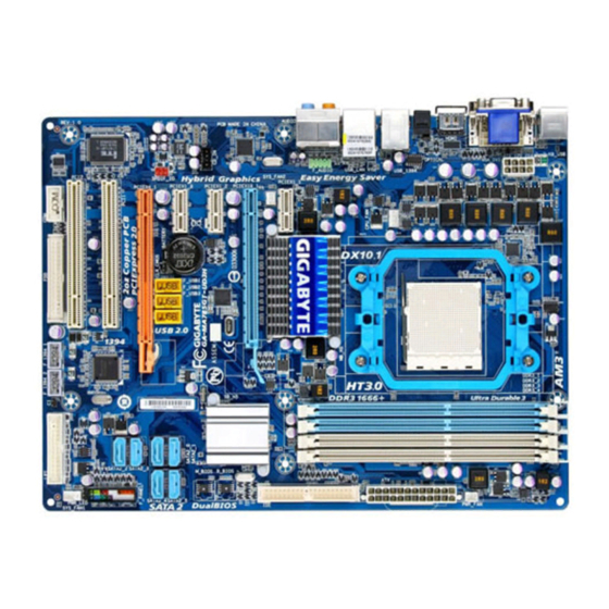
Page 10: Layout Diagram
USB Connector Connector RJ-45 over USB Connector ATA 133 IDE SYS FAN2 Conn. (IDE1) Audio Connector DDRIII 128Mb GPU Memory AMD 785G Chipset PCI Express2.0 x16 AMD SB710 Chipset by8-lane Gigabit LAN Chip CDIN HDMI-SPDIF Realtek ALC883 Serial-ATAII Connectors Audio Decode... - Page 11 Jumpers Jumper Name Description Page Keyboard/USB Power On Enabled/Disabled 3-pin Block JBAT Clear CMOS Header 3-pin Block Expansion Slots Socket/Slot Name Description Page ZIF Socket AM2 CPU Socket 940-pin PGAB Athlon64 CPU Socket DDRIII1,DDRIII2, DDRIII Module Socket 240-pin DDRIII Module Socket P.10 DDRIII3,DDRIII4 PCI1;PCI2...
-
Page 12: Chapter 2 Hardware Installation
Chapter 2 Hardware Installation Turn off your power when adding or removing expansion cards or WARNING! other system components. Failure to do so may cause severe damage to both your motherboard and expansion cards. Hardware installation Steps Before using your computer, you had better complete the following steps: 1. -
Page 13: Install Cpu
2. Forget password 3. After over clocking system boot fail JBAT JBAT 1-2 Closed Normal 2-3 Closed Clear CMOS CMOS RAM Clear Setting Install CPU 2-3-1 Glossary Chipset (or core logic) - two or more integrated circuits which control the interfaces between the system processor, RAM, I/O devises, and adapter cards. -
Page 14: About Amd Am3 Installation
2-3-2 About AMD AM3 CPU Installation This motherboard provides a socket AM3 surface mount, Zero Insertion Force (ZIF) socket, referred to as the mPGA940 socket supports AMD AM3 series processors. The CPU that comes with the motherboard should have a cooling FAN attached to prevent overheating. -
Page 15: Install Memory
Install Memory This motherboard provides four 240-pin DDRIII DUAL INLINE MEMORY MODULES (DIMM) socket for DDRIII memory expansion to maximum memory volume of 16 GB DDR SDRAM. Valid Memory Configurations Bank 240-Pin DIMM PCS Maximum Capacity DDRIII1 DDRIII800/DDRIII1066/DDRIII1333/DDRIII1600 DDRIII2 DDRIII800/DDRIII1066/DDRIII1333/DDRIII1600 DDRIII3 DDRIII800/DDRIII1066/DDRIII1333/DDRIII1600 DDRIII4... -
Page 16: Expansion Cards
Expansion Cards 2-5-1 Procedure For Expansion Card Installation 1. Read the documentation for your expansion card and make any necessary hardware or software setting for your expansion card such as jumpers. 2. Remove your computer’s cover and the bracket plate on the slot you intend to use. 3. -
Page 17: Connectors, Headers
PCI-E 2.0x16 Slotby8lane PCI-E 2.0x1 32-bit PCI Slots 2-6 Connectors, Headers 2-6-1 Connectors Power Connector (24-pin block): ATXPWR1 ATX Power Supply connector: This is a new defined 24-pins connector that usually comes with ATX case. The ATX Power Supply allows using soft power on momentary switch that connect from the front panel switch to 2-pins Power On jumper pole on the motherboard. - Page 18 (2)ATX 12V Power Connector (8-pin block): ATX12V This is a new defined 8-pins connector that usually comes with ATX Power Supply. The ATX Power Supply which fully supports Socket AM2+ processor must including this connector for support extra 12V voltage to maintain system power consumption.
- Page 19 (7) Primary IDE Connector (40-pin block): IDE1 This connector supports the provided IDE hard disk ribbon cable. After connecting the single plug end to motherboard, connect the two plugs at other end to your hard disk(s). If you install two hard disks, you must configure the second drive to Slave mode by setting its jumpers accordingly.
-
Page 20: Headers
(12) SPDIF Out connectors: SPDIF_Out1 The SPDIF output is capable of providing digital audio to external speakers or compressed AC3 data to an external Dolby digital decoder. Use this feature only when your stereo system has digital input function. 2-6-2 Headers (1) Line-Out/MIC Header for Front Panel (9-pin): AUDIO These headers connect to Front Panel Line-out, MIC connector with cable. - Page 21 method of rebooting in order to prolong the lift of the system’s power supply. See the figure below. (7) Power switch: PWR BTN This 2-pin connector connects to the case-mounted power switch to power ON/OFF the system. PWRLED Pin 1 JW FP SPEAK Pin 1...
- Page 22 (9) CD Audio-In Headers (4-pin): CDIN1 CDIN are the connectors for CD-Audio Input signal. Please connect it to CD-ROM CD-Audio output connector. CDIN CD Audio-In Headers (10) Serial COM Port header: COM1 COM1 is the 9-pin block pin-header. Pin1 Serial COM Port 9-pin Block (11) HDMI-SPDIF Out header: SPDIF Out The SPDIF output is capable of providing digital audio to external speakers or compressed AC3 data to an external Dolby digital decoder.
-
Page 23: Starting Up Your Computer
Starting Up Your Computer 1. After all connection is made, close your computer case cover. 2. Be sure all the switch are off, and check that the power supply input voltage is set to proper position, usually in-put voltage is 220V∼240V or 110V∼120V depending on your country’s voltage used. -
Page 24: Chapter 3 Introducing Bios
Chapter 3 Introducing BIOS The BIOS is a program located on a Flash Memory on the motherboard. This program is a bridge between motherboard and operating system. When you start the computer, the BIOS program will gain control. The BIOS first operates an auto-diagnostic test called POST (power on self test) for all the necessary hardware, it detects the entire hardware device and configures the parameters of the hardware synchronization. -
Page 25: The Main Menu
Press F1 to pop up a small help window that describes the appropriate keys to use and the possible selections for the highlighted item. To exit the Help Window, press <Esc>. The Main Menu AMI ® Once you enter BIOS CMOS Setup Utility, the Main Menu (Figure 3-1) will appear on the screen. -
Page 26: Standard Bios Features
Power User Overclock Settings Use this menu to specify your settings (frequency, Voltage) for overclocking demand BIOS Security Features Use this menu to set supervisor password and user password. Load Standard Defaults This menu uses a minimal performance setting, but the system would run in a stable way. -
Page 27: Advanced Bios Features
While entering setup, BIOS auto detest the presence of IDE devices. This displays the status of auto detection of IDE devices. Type: The optional settings are: Not Installed; Auto; CD/DVD and ARMD LBA/Large Mode: The optional settings are Auto; Disabled. Disabled: Disables LBA Mode. -
Page 28: Cpu Configuration
AGESA Version: 6.1.3.0 Physical Count: 1 Enable or Disabled the building of Logical Count: 4 ACPI SART Table AMD Phenom™II X4 945 processor Revision: C2 Cache L1: 512KB Cache L2 : 2048KB Cache L3 : 6MB Speed : 3000MHz, NB Clk : 200MHz Able to Change Freq. -
Page 29: Memoryconfiguration
NB Power Management Features Dynamic clock gating for IOC/NT/MCU/CFG. HDMI Audio Use this item to select HDMI audio, the optional settings are: Disabled and Enabled. Default is Enabled. Primary Video Controller This item is for user to choose primary video controller. 3-6-1 Memory Configuration CMOS Setup Utility-Copyright(C)1985-2005 American Megatrends. -
Page 30: Internal Graphices Configuration
Enable or Disable DDR power down mode. 3-6-2 Internal Graphics Configurations CMOS Setup Utility-Copyright(C)1985-2005 American Megatrends. Inc. Internal Graphics Configurations Internal Graphics Mode UMA+SIDEPORT Help Item UMA Frame Buffer Size Auto Options SIDEPORT Clock Speed 667MHz Disabled GFX Engine Clock Override Disabled SIDEPORT UMA-SP Interleave Mode... -
Page 31: Integrated Peripherals
Port #02 Features ~ Port #05 Features Press Enter and set values in the sub-items as Ge2 High Speed Mode, Link ASPM,. NB-SB Port Features Press Enter and set values in the sub-items as NB-SB Link ASPM; NP NB-SB VC1 Traffic Support and Link Width. -
Page 32: Super Io Configuration
Onboard PCIE Lan Use this item to enable or disable Onboard PCIE Lan HD Audio Azalia Device This item allows you to decide to enable/disable the chipset family to support HD Audio. The optional settings are: Auto; Enabled and Disabled. USB Configuration Press Enter to set values for sub-items as: Legacy USB Support, USB 2.0 Controller Mode BIOS EHCI Hand-OFF and so on. -
Page 33: Miscellaneous Control
Power Management Setup The Power Management Setup allows you to configure your system to most effectively save energy saving while operating in a manner consistent with your own style of computer use. CMOS Setup Utility-Copyright(C)1985-2005 American Megatrends. Inc. Power Management Setup Power Management Feature Help Item Power management/APM... -
Page 34: Pc Health Status
Yes: Let the operating system configure Plug and Play devices, not required for boot if your system has a Plug and Play system. Allocate IRQ for PCI VGA The optional settings are: No; Yes. Yes: Assigns IRQ to PCI VGA card if card requests IRQ. No: Does not assign IRQ to PCI VGA card even card requests an IRQ. -
Page 35: Thermal Throttling Options
3-10-1 Smart FAN Configuration CMOS Setup Utility-Copyright(C)1985-2005 American Megatrends. Inc. Smart FAN Configuration Help Item Fan1 Mode Setting Auto Fan by Duty Temperature1 Limit of Highes Temperature1 Limit of Second Fan Configuration Mode Setting Temperature1 Limit of Third Temperature1 Limit of Lowest ↑↓... -
Page 36: Power User Overclock Setting
Processor Voltage The optional settings are: Auto; 0.800V~1.350V. AOD Compatibility Choose Enabled means only AMD over drive can adjust voltage Choose Disabled means only BIOS can adjust voltage HT Link Speed The HyperTransport link will run at this speed of it is slower than or equal to the system clock and the board is capable. -
Page 37: Bios Security Features
3-13 BIOS Security Features CMOS Setup Utility-Copyright(C)1985-2005 American Megatrends. Inc. BIOS Security Features Help Item Security Settings Install or change the password Supervisor Password: Not Installed User Password: Not Installed Change Supervisor Password Press Enter Change User Password Press Enter Boot Sector Virus Protection Disabled ↑↓... - Page 38 Notice! The BIOS options in this manual are for reference only. Different configurations may lead to difference in BIOS screen and BIOS screens in manuals are usually the first BIOS version when the board is released and may be different from your purchased motherboard. Users are welcome to download the latest BIOS version form our official website.
-
Page 39: Chapter 4 Driver & Free Program Installation
Chapter 4 DRIVER & FREE PROGRAM INSTALLATION Check your package and there is A MAGIC INSTALL CD included. This CD consists of all DRIVERS you need and some free application programs and utility programs. In addition, this CD also include an auto detect software which can tell you which hardware is installed, and which DRIVERS needed so that your system can function properly. -
Page 40: Ati Install Ati Driver Pack
4-1 Install ATI Driver Pack 1. Click ATI when the MAGIC INSTALL 2. Click NEXT when ATI software driver pack MENU appears. appears. 3. Click “Yes” to accept the license 4. Click Express, recommended. agreement and start installation.. 5. Click Continue Anyway. 6. -
Page 41: Sound Install Hd Codec Audio Driver
Sound Install HD Codec Audio Driver 1. Click SOUND when MAGIC INSTALL 2. Click NEXT When Realtek High Definition MENU appears Audio driver windows appear 3. Click FINISH and restart your computer 4. Manual Sound Effect Setting 5. Devices and mixer setting 6. -
Page 42: Lan Install Gigabit Ethernet Nic Driver
NOTE: Please upgrade your Windows XP to Service Pack 1 / Windows 2000 to Service Pack 4 or later before you the HD Audio CODEC driver. 4-3 LAN Install Gigabit Ethernet NIC Driver 1 Click LAN when MAGIC INSTALL MENU 2. -
Page 43: Raid Install Ati Sata Driver And Utility
4-7 Fusion Download Fusion Drivers and Tools Click Fusion when Magic Install menu appears to visit AMD official website http://game.amd.com/us-en/drivers_fusion.aspx?p=1 to download fusion drivers and tools. Please make sure that you net is connected well and you operating system is Windows Vista before... -
Page 44: Hdmi Installati Hdmi Audio Driver
4-8 HDMI Install ATI HDMI Audio Driver 1. Click HDMI when MAGIC INSTALL 2. Click Next on Install shield wizard MENU appears Window appears 3. Choose finish. 4-9 OVERCLOCK Install OVERCLOCK Drive Utility 1. Click OVER CLOCK when MAGIC 2. Click Next INSTALL MENU appears... - Page 45 3. Read the information, then click next. 4. Choose “I accept the terms in the license agreement”. 5. Choose “Anyone who use this computer” 6. The information describe the installation, Click Next. Click Next. 7. Choose Yes and Next. 8. Ready to install the program, click Install. 9.
- Page 46 “A:\xxxxxx.BAT”(xxxxxxx being the file name of the latest BIOS ) STEP 4. Type Enter to update and flash the BIOS. The system will restart automatically when BIOS is upgraded. 4-11 AMD Platform RAID Function Installation Please set these choice in the BIOS as RAID:BIOS setup \Integrated Peripherals \Onchip SATA Device \ Onchip SATA Type.
- Page 47 [figure3] Press [2] key, the interface of RAID, as figure 4. RAID function: RAID 0/ RAID 1/ RAID 10 [figure4] Choose LD 1 then press Enter. Take Raid0 for example, use [↑] [↓] to shift the cursor, press space key to change the choice, press [Ctrl-Y] to keep.
- Page 48 [figure5] [figure6] Press [3], delete the RAID mode, as figure 7.press [Delete] will delete the array. As figure 7. [figure7] Press [4], showing the information of controller, as figure 8.
- Page 49 [figure8] Making RAID driver diskette before Install WindowsXP/2000/Vista/Windows7 Before you install the operating system, you will need to make a RAID driver diskette before you start to install the Operating System. How to make a RAID driver diskette? 1: Insert the diskette which is being formatted in floppy drive on a system which can start OS.
- Page 50 4-12 G.P.I Function LED Display: PP_LED Lights off. It means the motherboard in the G.P.I mode. CPU works with the low power consumption. PP_LED Lights on. It means that the CPU works with high power consumption.
- Page 51 Power Supply Mold As a result of the increasing power consumption demand from many AMD CPUs in current market, we suggest not to use a CPU that demands more than 65W power consumption at work for an AMD CPU compliant board that comes with power supply design...
- Page 52 Subject 2: Suggestion on choosing electric fan Both the amount of electric current to MOSFET and the heat produced from the motherboard go up as AMD’s CPU power consumption increases. In this case we recommend users select a CPU fan with air outlet towards MOSFET so that CPU fan can carry away heat produced by MOSFET, for better heat dissipation effects.
Need help?
Do you have a question about the AMD 785G and is the answer not in the manual?
Questions and answers