Table of Contents
Advertisement
Quick Links
S
U
ER'S MANUAL
Of
AMD 770 & AMD SB710 Chipset
Based
M/B For AMD Socket AM3 Processor
NO. G03-HA10DELUXE-F
:
Rev
1.0
Release date: March, 2010
Trademark:
* Specifications and information contained in this documentation are furnished for information use only, and are
subject to change at any time without notice, and should not be construed as a commitment by manufacturer.
Advertisement
Table of Contents

Related Manuals for AMD 770


Summary of Contents for AMD 770
- Page 1 ER'S MANUAL AMD 770 & AMD SB710 Chipset Based M/B For AMD Socket AM3 Processor NO. G03-HA10DELUXE-F : Release date: March, 2010 Trademark: * Specifications and information contained in this documentation are furnished for information use only, and are subject to change at any time without notice, and should not be construed as a commitment by manufacturer.
- Page 2 Environmental Protection Announcement Do not dispose this electronic device into the trash while discarding. To minimize pollution and ensure environment protection of mother earth, please recycle.
-
Page 3: Table Of Contents
TABLE OF CONTENT ENVIRONMENTAL SAFETY INSTRUCTION ..............iii USER’S NOTICE ........................... iv MANUAL REVISION INFORMATION ..................iv COOLING SOLUTIONS........................ iv CHAPTER 1 INTRODUCTION OF AMD 770 MOTHERBOARDS FEATURES OF MOTHERBOARD ................1 1-1.1 SPECIAL FEATURES OF MOTHERBOARD ..........2 SPECIFICATION ......................4 PERFORMANCE LIST.................... -
Page 4: Environmental Safety Instruction
Environmental Safety Instruction Avoid the dusty, humidity and temperature extremes. Do not place the product in any area where it may become wet. 0 to 40 centigrade is the suitable temperature. (The figure comes from the request of the main chipset) Generally speaking, dramatic changes in temperature may lead to contact malfunction and crackles due to constant thermal expansion and contraction from the welding spots’... -
Page 5: User's Notice
Please refer to AMD official website for collection of heatsinks evaluated and recommended for Socket AM3 processors by AMD. In addition, this collection is not intended to be a comprehensive listing of all heatsinks that support Socket-AM3... -
Page 6: Chapter 1 Introduction Of Amd 770 Motherboards Features Of Motherboard
Multi-GPU configurations. This high bandwidth architecture in the AMD 770 chipset is with the flexibility for single or dual card configurations. The AMD 770 chipset provides one PCI Express 2.0 x16 by 16 lanes and one PCI Express 2.0 x16 by 4 lane slot to support simultaneous operation... -
Page 7: 1-1.1 Special Features Of Motherboard
1-1.1 Special Features of Motherboard AAA AMD Netbar Recommended Configuration AMD Company is in order to be able to better help Netbar users to provide a comprehensive and overall solution; to solve the problems that Netbar users encounter in pre-sale, sale and after-sale problems. Meanwhile to increase the AMD products awareness at the Netbar and enhance the Netbar users’... - Page 8 thereby enhancing the computer's performance and extending the life of the motherboard. 3D Audio—(3D Audio Sound Effect) OP with two-stage Butterworth filter and quadruple noninverting amplifier enhances bass effect under the 100MHz range to perfect audio effect, brings you stunning shock experience in video game, true-to-life simulated feeling when watching films and the greatest touch as that in the concert.
-
Page 9: Specification
ATX form factor,size: 29.5cm x23.0cm Design AMD770 North Bridge Chipset Chipset AMD SB710 South Bridge Chipset Support Phenom II x 4; Phenom II x 3; Phenom II x2; Athlon II x4; Athlon II x3; Athlon II x2; Sempron series AM3 CPU Socket AM3 CPU in the 125W range Support HT 3.0... -
Page 10: Performance List
1-3 Performance List The following performance data list is the testing result of some popular benchmark testing programs. These data are just referred by users, and there is no responsibility for different testing data values gotten by users (the different Hardware & Software configuration will result in different benchmark testing results.) Performance Test Report Performance Test Report... -
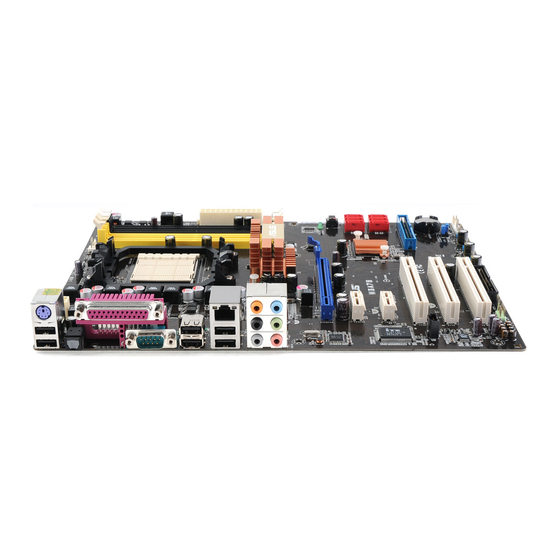
Page 11: Layout Diagram
RJ-45 Over USB Connector (UL1) Thunder-lightning Protection ATA 133 IDE Conn. (IDE1) Audio Connector (CN2) AMD 770 Chipset Memory Anti-theft Lock Gigabit LAN Chip SYSFAN1 AMD SB710 Chipset PCI Express 2.0 x16 8MBit DIP Flash Serial-ATAII Connectors By 16-lane ROM BIOS... - Page 12 SPDIF Out header 2-pin Block P.19 Expansion Sockets Socket/Slot Name Description Page ZIF Socket AM3 CPU Socket AMD AM3 CPU Socket P.10 DDRIII1~DDRIII4 DDRIII Module 240-pin DDRIII Module Socket P.11 Socket PCI Slots 32-bit PCI Local Bus Expansion slots P.13 PCI1∼ PCI2 PCI-Express 2.0 x1...
-
Page 13: Chapter 2 Hardware Installation
Chapter 2 Hardware Installation Turn off your power when adding or removing expansion cards or WARNING! other system components. Failure to do so may cause severe damage to both your motherboard and expansion cards. 2-1 Hardware installation Steps Before using your computer, you had better complete the following steps: 1. -
Page 14: Install Cpu
JBAT 1-2 Open: Normal 1-2 Short: CMOS Clear CMOS Clear Setting Install CPU 2-3-1 Glossary Chipset (or core logic) - two or more integrated circuits which control the interfaces between the system processor, RAM, I/O devises, and adapter cards. Processor socket- the socket used to mount the system processor on the motherboard. -
Page 15: About Amd Am3 Cpu Installation
2-3-2 About AMD AM3 CPU Installation This motherboard provides a socket AM3 surface mount, Zero Insertion Force (ZIF) socket, referred to as the mPGA socket supports AMD AM3 processor. The CPU that comes with the motherboard should have a cooling FAN attached to prevent overheating. -
Page 16: Install Memory
2-4 Install Memory This motherboard provides four 240-pin DDR III DUAL INLINE MEMORY MODULES (DIMM) socket for DDR III memory expansion available to maximum memory volume of 16GB DDRIII SDRAM. Valid Memory Configurations Bank 240-Pin DIMM Maximum Capacity Bank 0, 1 (DDRIII1) DDRIII 800/DDR III 1066/ DDR III1333 Bank 2, 3 (DDRIII2) DDRIII 800/DDR III 1066/ DDR III1333... -
Page 17: Expansion Cards
Expansion Cards 2-5-1 Procedure for Expansion Card Installation 1. Read the documentation for your expansion card and make any necessary hardware or software setting for your expansion card such as jumpers. 2. Remove your computer’s cover and the bracket plate on the slot you intend to use. -
Page 18: Pci Express2.0 Slot
2-5-3 PCI Express2.0 Slot AMD770 Series motherboard series offer one PCI-Express2.0x16 by16-lane graphics slot and one PCI Express 2.0 x 16 by 4-lane slot. One PCI Express2.0 x1 I/O slot tackling the most demanding multimedia tasks nowadays. The AMD770 motherboards also carry two 32-bit PCI slots guarantee the rich connectivity for the I/O peripheral devices. - Page 19 (2) ATX 12V Power Connector (8-pin block) : ATX12V1 This is a new defined 8-pin connector that usually comes with ATX Power Supply. The ATX Power Supply which fully supports AMD AM3 processor must including this connector for support extra 12V voltage to maintain system power consumption.
- Page 20 (3) PS/2 Mouse & PS/2 Keyboard Connector: KB The connectors are for PS/2 keyboard and PS/2 Mouse. (4) USB Port connector: CN1/ UL1 for USB The connectors are 4-pin connector that connects USB devices to the system board. (5) LAN Port connector: UL1 for RJ45 LAN The connector is standard RJ45 connector for Network.
-
Page 21: Headers
• Two hard disks can be connected to each connector. The first HDD is referred to as the “Master” and the second HDD is referred to as the “Slave”. • For performance issues, we strongly suggest you don’t install a CD-ROM or DVD-ROM drive on the same IDE channel as a hard disk. - Page 22 Pin 1 USB Port Header (3) Speaker connector: SPEAK1 This 4-pin connector connects to the case-mounted speaker. See the figure below. (4) Power LED: PWR LED The Power LED is light on while the system power is on. Connect the Power LED from the system case to this pin.
- Page 23 CPUFAN SYSFAN1 SYSFAN2 (9) CD Audio-In Headers (4-pin): CDIN1 CDIN are the connectors for CD-Audio Input signal. Please connect it to CD-ROM CD-Audio output connector. CDIN CD Audio-In Headers (10) IR infrared module Headers (5-pin): IR1 This connector supports the optional wireless transmitting and receiving infrared module.
- Page 24 Pin 1 PARALLEL Connector (12) SPDIF Out header: HDMI_SPDIF The SPDIF output is capable of providing digital audio to external speakers or compressed AC3 data to an external Dolby digital decoder. Use this feature only when your stereo system has digital input function. Some VGA cards need to connect SPDIF-In Header, HDMI-SPDIF Port on the VGA card can there be sound output.
-
Page 25: Starting Up Your Computer
Starting Up Your Computer 1. After all connections are made, close your computer case cover. 2. Be sure all the switch are off, and check that the power supply input voltage is set to proper position, usually in-put voltage is 220V∼240V or 110V∼120V depending on your country’s voltage used. -
Page 26: Chapter 3 Introducing Bios
Chapter 3 Introducing BIOS The BIOS is a program located on a Flash Memory on the motherboard. This program is a bridge between motherboard and operating system. When you start the computer, the BIOS program will gain control. The BIOS first operates an auto-diagnostic test called POST (power on self test) for all the necessary hardware, it detects the entire hardware device and configures the parameters of the hardware synchronization. -
Page 27: The Main Menu
Press F1 to pop up a small help window that describes the appropriate keys to use and the possible selections for the highlighted item. To exit the Help Window, press <Esc>. The Main Menu Once you enter AMI BIOS Setup Utility, the Main Menu (Figure 3-1) will appear on the screen. -
Page 28: Standard Bios Features
Use this menu to specify your settings for Netbar User demand. User Overclock Settings Use this menu to specify your settings (frequency, Voltage) for overclocking demand. BIOS Security Features This entry for setting Supervisor password and User password. Load Optimal Defaults Use this menu to load the BIOS default values these are setting for optimal performances system operations for performance use. -
Page 29: Advanced Bios Features
System Time The time format is <hour><minute><second>. IDE Channel 0 Master / Slave SATA Channel 1, 2, 3, 4 While entering setup, BIOS auto detest the presence of IDE devices. This displays the status of auto detection of IDE devices. Type: The optional settings are: Not Installed;... -
Page 30: Advanced Chipset Features
Boot Up NumLock Status The default value is on. On (default) Keypad is numeric keys. Keypad is arrow keys. Advanced Chipset Features The Advanced Chipset Features Setup option is used to change the values of the chipset registers. These registers control most of the system options in the computer. 3-6-1 PCI Express Configuration Port #02 Features Press Enter and set values in the sub-items as Gen2 High Speed Mode, Link ASPM,... -
Page 31: Integrated Peripherals
Port #04 Features; Port #09Features; Port #10 Features Press Enter and set values in the sub-items as Gen2 High Speed Mode, and Link ASPM. NB-SB Port Features Press Enter and set values in the sub-items as NB-SB Link ASPM and NP NB-SB VC1 Traffic Support. -
Page 32: Power Management Features
Use this item to configures the USB 2.0 Controller in HiSpeed(480Mbps) or FullSpeed(12 Mbps). BIOS EHCI Hand-Off The optional settings are: Enabled and Disabled. This is a workaround for OSes without EHCI hand-off support. The EHCI ownership change should claim by EHCI driver. -
Page 33: Miscellaneous Control
Disable /enable RTC to generate a wake event. 3-9 Miscellaneous Control Clear NVRAM The optional settings are: No; Yes. Use this item to clear NVRAM during system boot. Plug & Play O/S The optional settings are: No; Yes No: Let the BIOS configure all the devices in the system. Yes: Let the operating system configure Plug and Play devices, not required for boot if your system has a Plug and Play system. -
Page 34: Pc Health Status
Thermal Cruise Mode; Speed Cruise Mode; Smart FAN III Mode. 3-11 Netbar User Setting Onboard Lan BootROM Use this item to enable or disable PXE Function. AMD Cool&Quiet Control Use this item to enable or disable the generation of ACPI_PPC, _PSS, and _PCT objects. -
Page 35: User Overclock Settings
Processor Voltage The optional settings are: Auto; 0.800V~1.350V. AOD Compatibility Choose Enabled means only AMD over drive can adjust voltage. Choose Disabled means only BIOS can adjust voltage. CPU Vcore 7-Shift Use this item to set value in CPU Vcore 7-Shift function. The optional settings are: Defaults and100 mv. -
Page 36: Cpu Configuration
3-12-1 CPU Configuration GART Error Reporting This option should remain disabled for the normal operation. The driver developer may enable it for testing purpose. ACPI SRAT Table Use this item to enable or disable the building of ACPI SRAT Table. 3-13 BIOS Security Features You can set either supervisor or user password or both of them. - Page 37 are: Supervisor password: Can enter and change the options of the setup menus. User password: Can only enter but do not have the right to change the options of the setup menus. When you select this function, the following message will appear at the center of the screen to assist you in creating a password.
-
Page 38: Load Optimal/ Standard Defaults
3-14 Load Optimal Defaults/ Load Standard Defaults Load Optimal Defaults When you press <Enter> on this item, you get a confirmation dialog box with a message similar to: Pressing <OK> loads the default values that are factory settings for optimal performance system operations. -
Page 39: Chapter 4 Driver & Free Program Installation
Chapter 4 Driver & Free Program Installation Check your package and there is A MAGIC INSTALL CD included. This CD consists of all DRIVERS you need and some free application programs and utility programs. In addition, this CD also include an auto detect software which can tell you which hardware is installed, and which DRIVERS needed so that your system can function properly. -
Page 40: Ati Install Ati South Bridge Driver Pack
4-1 ATI Install ATI South Bridge Drive Pack 1. Click ATI in the Magic Install Menu 2. Click Next when WIindows XP ATI South appears. Bridge drivers Setup appears. 3. Click “Yes” to accept the license 4. Click Finish and select if restart the agreement. - Page 41 3. Select one of the following options and 4. Manual Sound Effect Setting. click OK to finish setup. 5. mixer setting. 6. Audio input and output setting. 7. Microphone effect setting. 8. 3D demo setting. NOTE: Please upgrade your Windows XP to Service Pack 1 / Windows 2000 to Service Pack 4 or later before you the HD Audio CODEC driver.
-
Page 42: Lan Install Gigabit Ethernet Nic Driver
Install Gigabit Ethernet NIC Driver 4-3 LAN 1. Click LAN when Magic Install Menu appears. 2. Click Next, install Realtek GbE&FE Ethernet PCI-E NIC Driver. 3. Click install to begin the installation. 4. After driver installation completed, Click Finish. 4-4 RAIDDISK Install ATI SATA Driver and Utility 1 Click RAIDDISK when Magic Install Menu 2. -
Page 43: Norton Installnorton 2010 Anti-Virus Program
Norton Install Norton 2010 Anti-virus Program 1 Click Norton when Magic Install menu 2. Click Agree & Install after reading Unser appears. License Agreement. 4-6 PC-Health Install MyGuard Hardware Monitor Utilit 1. Click PC-HEALTH when Magic Install 2. Click Next on Install shield wizard Window MENU appears appears 3. -
Page 44: How To Update Bios
STEP 4. Type Enter to update and flash the BIOS. The system will restart automatically when BIOS is upgraded. 4-8 AMD Platform RAID Function Installation Please set these choice in the BIOS as RAID:BIOS setup \Integrated Peripherals \Onboard SATA Device \ Onchip SATA Type. When the below figures appeared,... - Page 45 [figure2] press[1] key,showing the RAID,as the below figure [figure3] Press [2] key, build the interface of RAID, as figure 4. RAID function: 1. RAID 0 2. RAID 1 3. RAID 10 4. RAID JBOD...
- Page 46 [figure4] Choose LD 1 then press Enter. Take Raid0 for example, use [↑] [↓] to shift the cursor, press space key to change the choice, press [Ctrl-Y] to keep. Set Assignment mode as [Y], press [Ctrl-Y] to keep, then figure 5 appeared, erase the MBR.
- Page 47 OS. 2: After booting OS insert the bundle CD in your CD-ROM. 3: Copy all the files from\AMD\RAID Disk to floppy diskette. Once you have the SATA driver diskette ready, you may start to install Windows XP, Windows 2000 or Windows vista or Windows 7 on your System.
-
Page 48: Pro Magic Plus Function Introduction
At this moment, please press <F6> key and follow the instructions of Windows XP or Windows 2000 for the proper installation. 4-9 Pro Magic Plus Function Introduction What’s Pro Magic Plus? Tired with reinstall OS each time when it doesn’t work? Does your computer often crash down or unable to work after installed new software? Have you had great loses and troubles because of computer problems? Still using time-consuming backup software that occupies lots of HD space? - Page 49 Functions of each version will differ from each other, and will be based on the function NOTE: descriptions of each version. System Requirements ◇ First OS must be Windows 2000/XP/Vista ◇ Support Only Windows OS (No Linux) ◇ Windows server OS and Windows NT not supported ◇...
-
Page 50: Function Led Display
4-10 G.P.I. Function LED Display PWS_LED4 PWS_LED3 PWS_LED2 PWS_LED1 All LED off or glitter. It means the motherboard in the G.P.I mode. CPU works with the low power consumption. PWS_LED4 PWS_LED3 PWS_LED2 PWS_LED1 Three LED off or glitter. It means the motherboard is working on partial power saving mode. - Page 51 Subject 1: Regarding the Application of 3-Phase or 3+1 Phase Power Supply Mold As a result of the increasing power consumption demand from many AMD CPUs in current market, we suggest not to use a CPU that demands more than 65W...
- Page 52 Both the amount of electric current to MOSFET and the heat produced from the motherboard go up as AMD’s CPU power consumption increases. In this case we recommend users select a CPU fan with air outlet towards MOSFET so that CPU fan can carry away heat produced by MOSFET, for better heat dissipation effects.
Need help?
Do you have a question about the 770 and is the answer not in the manual?
Questions and answers