Table of Contents
Advertisement
Quick Links
Advertisement
Table of Contents

Related Manuals for Cosmos XP-703D III


Summary of Contents for Cosmos XP-703D III
- Page 1 Semiconductor Manufacturing Gas Detector This instruction manual explains the use of three models listed on the left. Keep this Instruction Manual available for quick reference when needed. Read this Instruction Manual and thoroughly understand before using the product.
-
Page 2: Table Of Contents
Table of Contents Included in this Package ................1 1. Introduction .................... 2 Symbols ....................2 Safe Operation ..................3 2. Part Names and Functions ..............4 3. Operating Procedure ................7 Attachment of Drain Filter ................. 7 Operating Procedure ................8 Silent Mode (No Operation Sound) ............ -
Page 3: Included In This Package
Detector, be sure to check that all items have been provided. Every precaution has been taken in preparing the Gas Leak Detector. However, if any items are missing or damaged, please contact your New Cosmos distributor. Replacements for any missing or damaged items will be sent. -
Page 4: Introduction
1. Introduction Thank you for purchasing a New Cosmos Gas Leak Detector. Please read this Instruction Manual thoroughly before using the Gas Leak Detector to help prevent gas leakage accidents and to aid in safety inspections. XP-703DIII Gas Leak Detector detects leakage of semiconductor manufacturing gases and when the gas concentration exceeds the set value, a buzzer and lamp provide notification of the gas leakage to help prevent gas leak accidents. -
Page 5: Safe Operation
Safe Operation Be sure to observe the following to use the product safely and properly. At the time of the detection, the target gas may be discharged from the DANGER exhaustion port. DANGER. Do not inhale gas. DANGER. Keep away from the fire. ... -
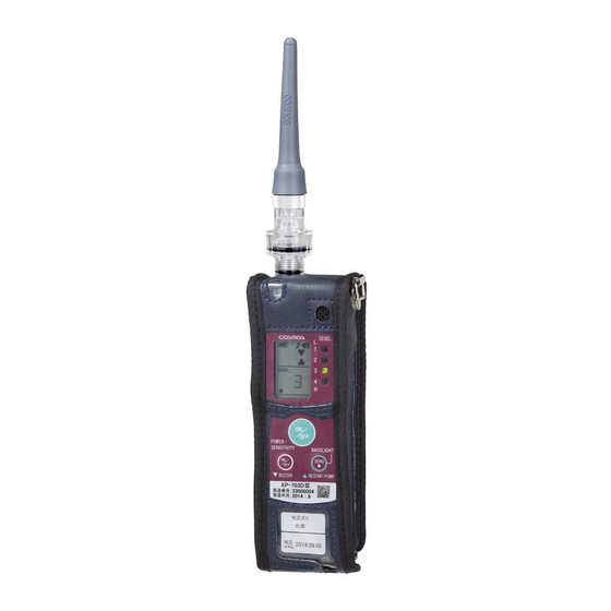
Page 6: Part Names And Functions
2. Part Names and Functions - 4 -... - Page 7 Name Functions AT-2B Attachment Gas inlet. Protects the Gas Leak Detector from water, dust, DF-114 Drain Filter and other foreign matter. Outlet Gas outlet to exhaust sampled gas. Turns the power ON and OFF. POWER/SENSITIVITY Button Sets the gas sensitivity level. Turns the alarm buzzer and operation sound ON BUZZER Button and OFF.
- Page 8 Soft case Name Functions Side Zipper Open the zipper to replace the batteries. Back Pocket The Operating Guide is stored here. Inside Pocket A Replacement Filter Element is stored here. - 6 -...
-
Page 9: Operating Procedure
3. Operating Procedure Attachment of Drain Filter Attach the Drain Filter and Attachment to the Gas Leak Detector before use. Place the Gas Leak Detector in the soft case, and close the zippers (both sides) and Velcro tape. (The Gas Leak Detector is in the soft case from the shipment.) Insert the Attachment to the Drain Filter. -
Page 10: Operating Procedure
Operating Procedure Always perform the daily check before use. (Refer to page 16.) WARNING Insert Turn ON Warm- Turn OFF STEPS concentration Detection batteries power power display 1. Insert the Batteries There are no batteries in the Gas Leak Detector at the point of purchase. Insert the enclosed batteries into the Gas Leak Detector. - Page 11 SENS. 3) When the warm-up operation is completed, the buzzer sounds once, a gas sensitivity lamp (green) lights, and the gas sensitivity level is displayed on the LCD. The gas sensitivity level is set to level “3” immediately after the batteries are inserted. It starts up next time with the same settings of gas sensitivity level.
- Page 12 3. Zero Adjustment It needs to perform “Zero Adjustment” to use at sensitivity level “4”. CAUTION Due to its high sensitivity, it is too susceptible to the ambient environment to detect gas appropriately. It can be used even if the “Zero Point Status” (dot mark) is blinking or off, but it may not be able to detect gas properly.
-
Page 13: Silent Mode (No Operation Sound)
Move the Attachment towards the detection place. When the Gas Leak Detector detects a gas leak, the alarm lamp (red) will flash and the alarm buzzer will start sounding continuously. As the gas concentration increases, the alarm buzzer will sound more frequently and will change to continuous sound. (The alarm buzzer will sound faster as approaching the location of gas leak.) The alarm lamp (red) will flash and then light continuously in sync with the alarm buzzer. -
Page 14: Deactivating The Alarm Buzzer
In silent mode, the operation sound and alarm buzzer will not function and the operation sound and alarm sound indicators on the LCD will not be displayed. However, the error alarm buzzer and battery alarm buzzer (in unusable state) will sound. (Refer to SENS. -
Page 15: Error Displays
4. Error Displays If an error occurs with the Gas Leak Detector, the error lamps will flash, an error will be displayed on the LCD, and the buzzer will sound repeatedly. The major errors are described in the following table. Take the corresponding action given in the table. Error Error Display Cause... -
Page 16: Replacement Of Consumable Parts
5. Replacement of Consumable Parts Filter Element Replacement When the Filter Element is dirty or wet, or when the water or liquid is inside the Drain Filter, clean out the Drain Filter and replace the Filter Element. Do not replace the Filter Element while the Gas Leak Detector is CAUTION operating. -
Page 17: Battery Replacement
Battery Replacement NOTE Make sure to use size AA LR6 alkaline dry cell batteries. When the remaining battery charge indicator changes to , the battery charge is low. When the battery voltage drops and reaches to the final voltage, “E-B” (refer to Battery Alarm on page 13) will be displayed on the LCD and the Gas Leak Detector will not be working. -
Page 18: Maintenance Check
Replace the parts or request repairs. Periodic Inspection To maintain the accuracy of the Gas Leak Detector, request a periodic inspection at your New Cosmos distributor or directly from New Cosmos at least once a year. - 16 -... -
Page 19: Consumable Parts, Replacement Parts, And Options
Consumable Parts, Replacement Parts, and Options Part Name Model Part Code Remarks Filter Element (10pcs) FE-2 59160022 - Drain Filter DF-114 59070018 - Inspection Gas EG-10D 59150300 Attachment AT-2B 20524489 For tubing and coupling Instruction Manual - 17 -... -
Page 20: Troubleshooting
7. Troubleshooting Check for the items in the following table before requesting repair work. * If operation is impossible, try again after removing all of the batteries for a few minutes and insert them again. ■ Gas Leak Detector Problem Cause Action Reference... -
Page 21: Warranty
New Cosmos warrants to the original purchaser and no other person or entity (customer) that gas detection product supplied by New Cosmos shall be free from defects in materials and workmanship for a period of one (1) year from the date of purchase. This warranty does not include consumables, such as fuses, filters, etc. -
Page 22: Specifications
9. Specifications Model XP-703DⅢ Target Gas , AsH , SiH , PH Detection Principle Hot-wire semiconductor sensor (Refer to page 21.) Gas Sampling Method Extractive type : 5.07 x 10 , AsH : 2.53 x 10 : 1.01 x 10 , SiH : 2.53 x 10 Detectable Leak Rate... -
Page 23: Detection Principle
10. Detection Principle Hot-wire Semiconductor Sensor The sensor is constructed of a metal oxide semiconductor that is sintered in a ball on a platinum wire coil that functions as both a heater and electrode. It detects the change of electrical conductivity occurred by oxidation reaction and adsorption of combustible gas on the surface of the oxide semiconductor. - Page 24 Head Office New Cosmos Electric Co., Ltd. 2-5-4 Mitsuya-naka Yodogawa-ku Osaka 532-0036, Japan Tokyo Branch New Cosmos Electric Co., Ltd. 2-6-2, Hamamatsu-cho, Minato-ku Tokyo 105-0013 Japan Phone 81-3-5403-2715 Fax 81-3-5403-2710 Email: e-info@new-cosmos.co.jp URL: http://www.new-cosmos.co.jp XP-703DⅢCEET(03)1907.100...
Need help?
Do you have a question about the XP-703D III and is the answer not in the manual?
Questions and answers