
Related Manuals for Cosmos PS-7


Summary of Contents for Cosmos PS-7
- Page 1 New Cosmos PS-7 User Manual Includes: Product Manual Administrator Manual Pyrolyzer Manual...
- Page 2 PS-7 Manual © DOD Technologies, INC 675 Industrial Drive Bldg. A. Cary, IL 60013 Phone 815.788.5200 • Fax 815.788.5300 DC-ITD-PS7MAN01.A www.dodtec.com JAN 2019 815-788-5200...
-
Page 3: Table Of Contents
PS-7 Manual Table of Contents Chapter 1 – Introduction ............................5 Explanation of Symbols ..............................5 Chapter 2 – Safety Instructions ..........................6 Chapter 3 – Contents of This Package ........................7 3.1 End of Line Filter Use ................................8 Chapter 4 –... - Page 4 PS-7 Manual 2.1 Span Adjustment ................................51 2.2 21Vol% Adjustment ................................52 2.3 Changing Setting Values ..............................53 2.4 Changing the Alarm Settings ............................. 55 Pyrolyzer Manual ..............................57 Chapter 1 – Attach/Replacing the Pyrolyzer ....................... 58 DC-ITD-PS7MAN01.A www.dodtec.com JAN 2019...
-
Page 5: Chapter 1 - Introduction
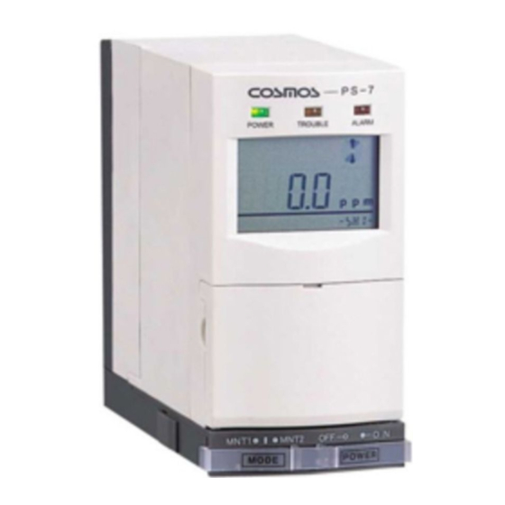
PS-7 Manual Chapter 1 – Introduction Thank you for purchasing the extractive COSMOS Gas Detector Model PS-7. This Gas Detector is designed to detect the leakage of toxic and combustible gases. It is designed to display the concentration level of detected gases on the main unit and output that information externally as an analog signal. -
Page 6: Chapter 2 - Safety Instructions
PS-7 Manual Chapter 2 – Safety Instructions Read and understand the following information to ensure that the Gas Detector is used correctly. The Gas Detector must always be used in accordance with relevant laws and regulations, and all wiring, installation, and other work associated with the Gas Detector must be performed by qualified personnel. -
Page 7: Chapter 3 - Contents Of This Package
2. When it is with DeviceNet unit, the contents are as described in the DeviceNet Unit Instruction manual IMPORTANT NOTICE - If using the PS-7 for absorbent / corrosive gases such as HCl, HF, Cl2, HBr, etc. You must remove the internal filter and install #2-800-013 OR #60009 Corrosive Filter at the end of the sample line. -
Page 8: End Of Line Filter Use
PS-7 Manual 3.1 End of Line Filter Use PN: 780248 PN: 60009 PN: 2-800-013 Use with Use with: Use with: AsH3 BCl3 BCl3 COCl2 C4F8 C5F8 B2H6 H2Se GeH4 SiCl4 SiCl4 SiF4 SiF4 CH2F2 POCl3 POCl3 Hydrazine Hydrazine CHF3 SiH4 DC-ITD-PS7MAN01.A... -
Page 9: Chapter 4 - System Flow Diagram
PS-7 Manual Chapter 4 – System Flow Diagram MF-50 (Dust filter) Sampling Unit Sensor Pump GAS OUT GAS IN Rc 1/4 Rc 1/4 Flow sensor GAS IN Controller Rc 1/4 Power DC 24V CPU Board Analog Output 4 to 20 mA DC... -
Page 10: Chapter 5 - Description
PS-7 Manual Chapter 5 – Description 5.1 Components on the Main Unit Description Function (Green) Power lamp. Illuminates during regular monitoring POWER lamp operations. TROUBLE lamp (Yellow) The lamp blinks when trouble occurs. (Red) The lamp blinks when the concentration level of detected ALARM lamp gas exceeds that of the preset alarm level. - Page 11 PS-7 Manual Description Function Fuse 125 V, 0.5 A Base unit power switch The power switch for the base unit. Mounting holes Screw holes (5.5) for wall mounting. Terminal strip Used to connect external wiring. Main unit power switch The power switch for the main unit.
-
Page 12: Details Of The Key Switch Section
PS-7 Manual 5.2 Details of the Key Switch Section Description Display Function Span adjustment To carry out 21vol% adjustments. SPAN switch (For the COS-7 oxygen sensor unit.) To carry out zeroing. Zeroing switch ZERO (For the CHS-7 flammable gas sensor unit or CDS-7 toxic gas sensor unit.) -
Page 13: Details Of The Lcd Screen Display
PS-7 Manual 5.3 Details of the LCD Screen Display Meaning Shows the detected gas concentration (with units). Lights when the flow rate is decreasing. (Also, see no. 6 below.) These light when the detected gas concentration exceeds that of the preset alarm level. -
Page 14: Chapter 6 - Installation And Wiring
When detecting highly adsorbent gases remove the internal filter and install proper end of line filter (see page 8) • The sample distance on the PS-7 is 50 feet for non-absorbent gases and 30 feet for absorbent gases. FEP TEFLON tubing must be used with absorbent gases. Caution •... -
Page 15: Installing The Main Unit
PS-7 Manual 6.1 Installing the Main Unit 1. Determine the installation point and attach the base unit using two M4 8 screws. 2. Run a cable through the cable entry (the cutout hole near the bottom of the base unit) and connect to the terminal board. -
Page 16: Wiring Instructions
PS-7 Manual Warning Be sure to push the latches back as far as they will go. If the latches are not back behind the locked/ unlocked line, normal gas detection will not be performed. NOTE: The protection seal on the base unit is to protect the connector and internal piping when attaching the base unit. - Page 17 PS-7 Manual Warning • Be especially careful regarding the polarity of the trouble alarm (TA: plus, TC: minus.) as the circuit protection diodes are internalized, if the polarity is reversed, the trouble warning signal will not be output. • To avoid electric shock, always disconnect the power supply before performing any wiring operations.
-
Page 18: Chapter 7 - Operation
PS-7 Manual Chapter 7 – Operation 7.1 Operation Procedures Carry out operations in the following manner. Refer to the items inside each box for more detailed instructions (listed from the next page) DC-ITD-PS7MAN01.A www.dodtec.com JAN 2019 815-788-5200... - Page 19 PS-7 Manual Warning • Verify that the power supply voltage is 24 V DC 10%. • Before operating the Gas Detector, verify that the sensor unit correctly displays the type of gas to be detected and the full-scale value. Warning •...
- Page 20 PS-7 Manual 3. Analog adjustment in maintenance mode 2 The analog output of the main unit changes when the maintenance switch is set to 2. Adjustment should be carried out based on the following instructions as the analog output also differs depending on the sensor unit being used.
- Page 21 PS-7 Manual Measure the analog output (current) of “G” and “H” on the terminal board TB1 using a tester, etc. If it falls within the range shown below, go on to the next step. Measure the analog output (current) of “G” and “H”...
- Page 22 PS-7 Manual 1. Pull back to open 1. Pull back to open 2. Move knob to center to set to normal mode 2. Move knob to center to set to normal mode 4. If the sensor unit is not attached, refer to 9.2 Attach / Replacing the Sensor Unit, and attach the sensor unit.
- Page 23 PS-7 Manual 6. Begin self-diagnosis after the front lamp and the LCD screen have been on for over one second. When using the main detector for the first time, or when a new sensor unit with different settings (sensor units for which the target gases and full-scale values, etc.,...
- Page 24 PS-7 Manual 8. Check the various setting values The values of the various settings can be checked by pressing the up/down switch, “” or “” on the main unit. The setting values are displayed in the bottom right hand corner of the LCD Screen.
- Page 25 PS-7 Manual Center of the Alarm point setting switch screen Up/Down Switch Bottom right of the screen 9. Verifying the sampling flow rate (Check flow rate) - Check to see that the flow rotation rate is high, and the TROUBLE lamp (yellow) is off.
- Page 26 PS-7 Manual 10. Verifying airtight seal Disconnect the gas sampling pipe from the gas inlet and block the inlet with a finger completely. The flow rotation rate will then slow. By keeping the inlet blocked, it will eventually stop. Then, check to make sure the TROUBLE lamp (Yellow) is blinking.
- Page 27 PS-7 Manual Zeroing 21vol% Adjustment Toxic Gas Sensor Unit: CDS-7 Oxygen Sensor Unit: COS-7 Combustible Gas Sensor Unit: CHS-7 1. Set to maintenance mode (MNT1 or MNT2) 1. Set to maintenance mode (MNT1 or MNT2) Left: Maintenance 1 (MNT1) Left: Maintenance 1 (MNT1)
- Page 28 PS-7 Manual Warning Zeroing and 21vol% adjustment must be carried out in a clean environment. If they are done in a gas-filled environment, the correct level of gas concentration detected will not be given. 12. Affix the seal showing target gases to be detected in a clearly visible place on the front of the main body.
- Page 29 PS-7 Manual Gas alarm Gas alarm (2 Normal Trouble stage) stage) Green light Yellow blink Red blink Red blink FL O W ALARM1 ALARM1 LCD screen S E N S ALARM2 C O N V Alarm contact (ZA1) Alarm contact...
-
Page 30: Gas Alarm Operating Instructions
PS-7 Manual 7.2 Gas Alarm Operating Instructions When the concentration level of detected gas exceeds that of the preset alarm level, the alarm contacts are activated after a set time delay, the ALARM lamp (red) blinks, and ALARM1 or ALARM2 is displayed on the LCD screen. - Page 31 PS-7 Manual NOTE: The relationship between 1 level and 2 level alarm values of each alarm mode is as follows: DC-ITD-PS7MAN01.A www.dodtec.com JAN 2019 815-788-5200...
-
Page 32: Trouble Alarm Operating Instructions
PS-7 Manual 7.3 Trouble Alarm Operating Instructions The trouble alarm will be activated in the following situations. (The open collector will be ON in normal mode, and OFF during trouble or when the power is disconnected.) The TROUBLE lamp (yellow) will blink, and analog output will drop to below 0.6 mA. -
Page 33: Test Mode Settings And Operating Instructions
PS-7 Manual 7.4 Test Mode Settings and Operating Instructions 1. Settings Press the “TEST” key switch on the front of the main unit. When this is pressed once, it will go into test mode. When it is pressed again, it will return to normal mode. -
Page 34: Maintenance Mode Settings And Operating Instructions
PS-7 Manual 7.5 Maintenance Mode Settings and Operating Instructions 1. Settings There are two types of maintenance modes. (See the table below for the functions of each) Set the maintenance switch at the bottom of the from of the main unit to 1 [left], or 2 [right]... -
Page 35: Chapter 8 - Maintenance And Inspection
2 (MNT 2) to ensure the sensor is stable and not drifting before placing the PS-7 in the run position. The actual time for the sensor to stabilize will vary based on the sensor type. Once stable the sensor is ready to use. - Page 36 PS-7 Manual 1. Gas concentration indicator inspection Verify that the gas concentration value is indicated on the LCD screen and the unit is functioning normally. 2. Sampling flow rate inspection (Flow rate inspection) Check that the flow rate on the LCD screen is rotating quickly. (Refer to 7.1 Operation Procedures (9)).
- Page 37 PS-7 Manual Caution The alarm check conducted with the Test switch will also activate the gas alarm contact. For this reason, if alarm contacts are used for interlocking with external devices, be sure to check that the interlock be released prior to conducting the alarm test. Also, be sure to carry out alarm testing with the test switch after setting in maintenance mode.
-
Page 38: Chapter 9 - Replacing Consumables
PS-7 Manual Chapter 9 – replacing Consumables • The Gas Detector is designed to allow users to replace consumables. • Contact your local dealer to purchase consumables, or if further instruction is needed regarding their installation and replacement. 9.1 Replacing the Filter Element (FE-1) Use the following procedure to replace the filter element if it becomes dirty or clogged. -
Page 39: Attach/Replacing The Sensor Unit
PS-7 Manual 9.2 Attach/Replacing the Sensor Unit Warning Verify that the detected gas type and the full-scale value of the new sensor unit are the same as the sensor unit being replaced. Be sure to check that its expiration date has not passed. - Page 40 PS-7 Manual Remove by turning. The axis is here (fulcrum). 4. Insert a finger in the gap between the main body and the top of the sensor unit and pull back slightly. Then grasp the sides of the sensor unit and pull out.
-
Page 41: Replacing The Sampling Unit
PS-7 Manual 7. Push both the latches on the left, and right-hand sides of the base unit back in until locked/unlocked line can be seen. Push both latches back in. Locked/unlocked line Latch Warning Be sure to return the latches right back in. If the latches are not behind the locked/unlocked line, gas detection will not work properly. - Page 42 PS-7 Manual 1. Remove the sensor unit as described in 9.2 Attach/Replacing the Sensor Unit. 2. Press back while pushing on the lower section of the main body cover with both thumbs and remove the front panel. Direction to push with thumb The position to push from.
- Page 43 PS-7 Manual The axis is here (fulcrum) Front panel Main body cover The axis is here (fulcrum). *Be careful not to pinch the cables. Warning If used when not inserted properly, the sensor unit will not be airtight, and will therefore not detect gases properly.
-
Page 44: Chapter 10 - Troubleshooting
PS-7 Manual Chapter 10 – Troubleshooting If a problem occurs, check the following before contacting a service or sales representative. Problem Cause Remedy Reference The power switch on the base Turn the power switch to the 7.1 Operation procedures unit is turned OFF. -
Page 45: Chapter 11 - Specifications
PS-7 Manual Chapter 11 – Specifications Model PS-7 Principle Electrochemical sensor, hot-wire semiconductor sensor, galvanic cell sensor Sampling method Pump suction type (0.5 L/min, suction flow automatically controlled) Gas sampling pipe* Teflon OD6/ID4 mm, maximum tube length 20 m. Concentration display 4-digit digital LCD display(incl. -
Page 46: Chapter 12 - Warranty
Chapter 12 – Warranty New Cosmos Electric Company Limited, warrants its gas detection products against any defects in materials and workmanship under normal use and operating conditions, for a period of one year from the date of purchase. -
Page 47: Hot-Wire Semiconductor Sensor
PS-7 Manual 13.2 Hot-wire Semiconductor Sensor In the hot-wire semiconductor method, a semiconductor sensor is designed to measure the change of electrical conductivity initiated by adsorption of the electrons of combustible gases onto the surface of a metal oxide semiconductor heated with a platinum filament. When the semiconductor adsorbs these electrons, the electron concentration increases and the conductivity of the semiconductor rises. -
Page 48: Chapter 14 - Glossary
PS-7 Manual + +4e − Base metal electrode 2Pb→2Pb As a result, a current proportional to the concentration of oxygen in the air flows from the noble metal electrode to the base metal electrode through an external circuit. Since the current generated is dependent on temperature, a thermistor is used to compensate for the atmospheric temperature changes. -
Page 49: Administrator Manual
PS-7 Manual Administrator Manual • Operate this unit only after reading and fully understanding the content of this manual. • This Operation Manual was written for administrator use. Instructions for the basic operations of this unit are provided separately in the standard Operation Manual. Refer to the Operation Manual when necessary. -
Page 50: Chapter 1 - Passwords
PS-7 Manual Chapter 1 – Passwords Some of the settings on this unit (alarm settings, etc.) are password protected. This Operation Manual explains the following items: • Passwords • Changing settings 1.1 Password Protected Settings Span Adjustment Refer to 2.1 Span Adjustment 21vol% adjustment Refer to 2.2 21Vol% Adjustment... -
Page 51: Chapter 2 - Changing Settings
PS-7 Manual Chapter 2 – Changing Settings 2.1 Span Adjustment Toxic Gas Sensor Unit: CDS-7 Combustible Gas Sensor Unit: CHS-7 1. Set to maintenance mode (MNT1 or MNT2) Left: Maintenance 1 (MNT 1) Center: Normal Mode Right: Maintenance 2 (MNT 2) 2. -
Page 52: 21Vol% Adjustment
PS-7 Manual 7. Remove the calibration gas, check that the detected gas concentration is under that of the alarm value and restore to the normal mode (by switching the maintenance switch to the center). 2.2 21Vol% Adjustment Oxygen Sensor Unit: COS-7 1. -
Page 53: Changing Setting Values
PS-7 Manual 7. Remove the calibration gas and confirm that no alarm is displayed( is not shown). ALARM 1 , ALARM 2 Then, restore to the normal mode by switching the maintenance switch to the center. 2.3 Changing Setting Values Some of the setting values of the unit can be changed. - Page 54 PS-7 Manual Default value LCD Screen The function Adjustable Remarks Toxic: CDS-7 Indication to be set Range Oxygen: Combustible: COS-7 CHS-7 Time delay (secs.) of the gas d1 ** Time delay 1 d1 0 d1 0 0 to 99 sec alarm contact (1st level) Time delay (secs.) of the gas...
-
Page 55: Changing The Alarm Settings
PS-7 Manual 2.4 Changing the Alarm Settings The values of alarm settings on this unit can be changed. The method for changing them is explained here. 1. Release the password lock. (Refer to 1.2 Releasing the Password Lock.) 2. Press the AL switch until the alarm setting to be changed is displayed on the LCD display. - Page 56 PS-7 Manual NOTE: The relationship between 1 level and 2 level alarm values of each alarm mode is as follows: *A2 Value should always be greater than A1 value. DC-ITD-PS7MAN01.A www.dodtec.com JAN 2019 815-788-5200...
-
Page 57: Pyrolyzer Manual
PS-7 Manual Pyrolyzer Manual • Be sure to store this operation manual in a convenient location and consult it whenever necessary. • Operate this unit only after reading and fully understanding the content of this manual. • This Operation Manual was written for the pyrolyzer(option). Instructions for the basic operations of this unit are provided separately in the standard Operation Manual. -
Page 58: Chapter 1 - Attach/Replacing The Pyrolyzer
Notice • The Sensor Modules do not normally require gas calibration to be performed on site. Gas calibration of the sensor module is performed by New Cosmos at the time the sensor is manufactured. • The CDS sensors (electrochemical) have a life of 2 or more years depending on the specific sensor. - Page 59 PS-7 Manual 3. Removing the old pyrolyzer. Pull out the connector. When it is newly installed and there is no pyrolyzer, refer to step 6. 4. Push the 2 protrusions behind the pyrolyzer with your forefinger and middle finger. Left Side...
- Page 60 PS-7 Manual 7. Connect the connector of the pyrolyzer. 8. Put the pyrolyzer case cover. Push the cover lock knob upward and lock the pyrolyzer. 9. Switch the main unit power ON. Press the up/ down switch, “” or “” on the main unit and verify that the pyrolyzer failure alarm is ON.
Need help?
Do you have a question about the PS-7 and is the answer not in the manual?
Questions and answers