Table of Contents
Advertisement
Available languages
Available languages
Quick Links
Advertisement
Table of Contents

Related Manuals for CFM TF140-DC


Summary of Contents for CFM TF140-DC
- Page 1 Installation & Maintenance Instalación & Mantenimiento TF140-DC TRANQUIL BATHROOM FANS VENTILADORES SILENCIOSOS PARA BAÑOS READ AND SAVE THESE INSTRUCTIONS FOR FUTURE REFERENCE LEA Y GUARDE ESTAS INSTRUCCIONES PARA REFERENCIAS FUTURAS...
-
Page 2: Safety Instructions
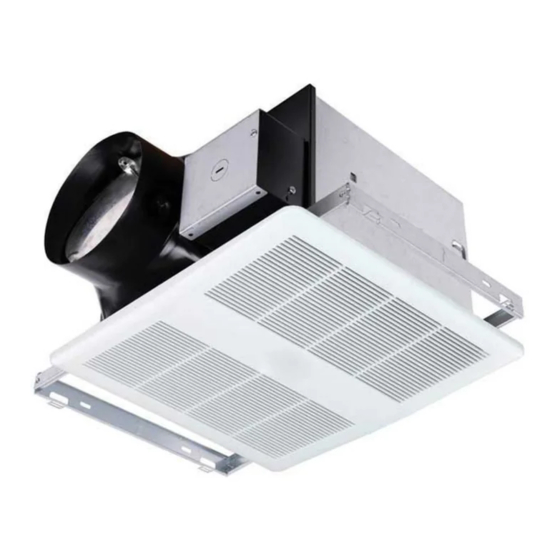
SAFETY INSTRUCTIONS NOTICE TF fans are not explosion proof and should not be used when a potentially ex- plosive situation exists. 1. Ensure that the electrical service to the fan is locked in the “OFF” position. Do not re-establish power supply until fan and activation device are completely installed. 2. - Page 3 TF TRANqUIL BATHROOM FANS MODELS: TF140-DC The delivery set includes: • Mounting frame • Housing • Duct assembly • Blower assembly • Grille • Mounting hardware 6” 7.625” TwO wAYS TO CONNECT DUCTwORk TO A UNIT...
-
Page 4: Fan Installation
FAN INSTALLATION WARNING Disconnect and lock out power supply before performing any installation work. Working on or near energized equipment could result in death or serious injury. Before installation, remove duct assembly and blower assembly. Mounting frame Housing Duct assembly Blower assembly STEP 1. -
Page 5: Step 5. Connect Wiring
FAN INSTALLATION STEP 3. INSTALL BLOwER ASSEMBLY Install the blower assembly in the housing and secure it with screws (Figure 3). STEP 4. CONNECT DUCT Using the recommended duct size, connect duct to the damper/duct connector (Figure 4), and run duct to an exterior roof or wall cap using the shortest, straightest duct routing possible. Ensure all duct connections are airtight. -
Page 6: Wiring Diagram
DIAGRAM MODEL: TF140-DC BROWN SWITCH I BLACK SWITCH II BLACK WHITE WHITE LINE GROUND GROUND UNIT JUNCTION BOX BLACK BLK WHITE WHT BROWN BRN GROUND GRD WIRE SWITCH I UNIT PANEL RECEPTACLE SWITCH II JUNCTION BOX POWER SUPPLY 120V AC... -
Page 7: Fan Operation
The Power Box, which is located inside the fan housing, has three separate adjustments: 1 2 3 a) Low Airflow knob adjusts the low airflow rate, ranging from a minimum 40 cfm to the desired airflow rate, which is deter- Low Air ow Time Delay Toggle mined by the Toggle Switch settings. -
Page 8: Troubleshooting
TROUBLESHOOTING WARNING Only qualified personnel should work on electrical equipment. Working on or near energized equipment could result in death or serious injury. 1. If the fan fails to start, consult wiring diagram to ensure proper connection. 2. Check the incoming supply for proper voltage. 3. - Page 9 ESPAÑOL INSTRUCCIONES DE SEGURIDAD ¡AVISO! Los ventiladores TF no están hechos a prueba de explosiones, y no deben usarse en situaciones donde haya riesgo de explosión. 1. Asegúrese que el suministro eléctrico del ventilador esté bloqueado en la posición “OFF”. No restablezca el suministro de energía hasta que el ventilador y el dispositivo de activación estén completamente instalados.
- Page 10 ESPAÑOL VENTILADORES SILENCIOSOS TF PARA BAñOS MODELO: TF140-DC El paquete de entrega incluye: • Marco para montar • Carcasa • Ensamble de ductos • Ensamble del soplador • Rejilla • Tornillería para montar 6” 7.625” DOS FORMAS DE CONECTAR EL SISTEMA DE DUCTOS A UNA UNIDAD.
- Page 11 ESPAÑOL INSTALACIÓN DEL VENTILADOR ¡ADVERTENCIA! Desconecte y apague el suministro de energía antes de realizar cualquier trabajo de instalación. Trabajar en o cerca de equipos energizados puede causar la muerte o lesiones graves. Antes de la instalación, desconecte el ensamble de los ductos y el del soplador. Marco para montar Carcasa Ensamble de ductos...
- Page 12 ESPAÑOL INSTALACIÓN DEL VENTILADOR PASO 3. INSTALAR ENSAMBLE SOPLADOR Instale el ensamble del soplador dentro de la carcasa, y fíjelo con tornillos (Fig. 3). PASO 4. CONECTAR DUCTO Usando el tamaño recomendado de ducto, conecte el ducto al conector de la compuerta/ducto (Fig.
-
Page 13: Diagrama De Cableado
ESPAÑOL DIAGRAMA DE CABLEADO MODELO: TF140-DC CAFÉ INTERRUPTOR I VENTILADOR NEGRO INTERRUPTOR II NEGRO CONECTOR BLANCO BLANCO DE ENTRADA TIERRA TIERRA UNIDAD CAJA DE CONEXIONES NEGRO BLANCO TIERRA CAFÉ PANEL DE INTERRUPTOR I CABLEADO UNIDAD RECEPTÁCULO DEL VENTILADOR INTERRUPTOR II... - Page 14 1 2 3 a) La perilla de flujo bajo de aire ajusta la velocidad baja del flujo de aire, que va desde un mínimo de 40 cfm al nivel de- Perilla de Flujo Perilla de Interruptor seado, y se determina por la configuración del interruptor de palanca.
-
Page 15: Solución De Problemas
ESPAÑOL SOLUCIÓN DE PROBLEMAS ¡ADVERTENCIA! Solo personal calificado debe trabajar con equipo eléctrico. Trabajar en o cerca de equipo energizado podría causar la muerte o lesiones graves. 1. Si el ventilador no se enciende, consulte el diagrama de cableado para asegurarse de que está conectado correctamente. -
Page 16: Acceptance Certificate
Due to constant product improvements, some models may differ slightly from those portrayed in this manual. Debido a las constantes mejoras del producto, algunos modelos pueden variar levemente de los que se presentan en este manual. TF140-DC FAN-I&M-1810 Continental Fan Manufacturing Inc. Continental Fan Canada Inc.
Need help?
Do you have a question about the TF140-DC and is the answer not in the manual?
Questions and answers