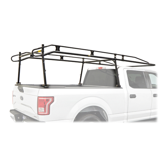
Summary of Contents for Kargo Master 90001
- Page 1 Installation Guide 90001 Kargo Master Rancho Cordova, CA 95742 800-343-7486 CustomerService@KargoMaster.com 20210922R1 DATE: ________________...
-
Page 2: Before You Begin
Read all instructions prior to assembling or installing any Kargo Master product. Follow each step in proper sequence, for ease and speed in assembling your Kargo Master rack. PROPER SEALANT APPLICATION IS CRITICAL TO ENSURE SOLID ASSEMBLY, PREVENTING RATTLING, AND WATER PENETRATION INSIDE THE RACK. -
Page 3: Table Of Contents
Instructions – 90001 Table of Contents Before You Begin ............................... 1 Parts .................................. 3 Hardware (18-90001) ............................4 Hardware (18-00001GM) ..........................6 Hardware (18-90001M) ............................ 6 Sealant Application ............................8 Installation Notes .............................. 8 Step 1A – Install Feet – Standard Installation: ....................9 Step 1B –... -
Page 4: Parts
Instructions – 90001 Parts For Technical Support Call: 800-343-7486, Monday-Friday, 7AM - 4 PM (PST) Page 3... -
Page 5: Hardware (18-90001)
Instructions – 90001 Hardware (18-90001) For Technical Support Call: 800-343-7486, Monday-Friday, 7AM - 4 PM (PST) Page 4... - Page 6 Instructions – 90001 Hardware (18-90001) (Continued) For Technical Support Call: 800-343-7486, Monday-Friday, 7AM - 4 PM (PST) Page 5...
-
Page 7: Hardware (18-00001Gm)
Instructions – 90001 Hardware (18-00001GM) Hardware (18-90001M) For Technical Support Call: 800-343-7486, Monday-Friday, 7AM - 4 PM (PST) Page 6... - Page 8 Instructions – 90001 TRUCK RACK EXPLODED VIEW For Technical Support Call: 800-343-7486, Monday-Friday, 7AM - 4 PM (PST) Page 7...
-
Page 9: Sealant Application
Instructions – 90001 DO NOT EXCEED MANUFACTURERS WEIGHT CAPACITY FOR ROOF Sealant Application Proper sealant application is critical to preventing water penetration inside the rack AND provides for a stable connection between parts. Apply a healthy bead of sealant entirely around every swaged joint as shown. Improper sealing can lead to water penetration. -
Page 10: Step 1A - Install Feet - Standard Installation
Instructions – 90001 Step 1A – Install Feet – Standard Installation: Position a footplate on the bedrail, as far forward as possible, with the inside of the bed is against the downward flange on the foot. Position a second footplate on the bedrail, with the foot U-bracket saddle located near the rear stake pocket. - Page 11 Instructions – 90001 Rear Foot Stake Pocket - Ford and Chevy: STAKE POCKET CUT AWAY VIEW Remove taillight. A T15 Torx wrench is supplied to remove Chevy taillights. On the rear foot only, insert the 3/8” x 8” button...
-
Page 12: Step 1B - Permanent Installation
Instructions – 90001 Step 1B – Permanent Installation: Position front footplate on the truck bedrail, as far forward as possible, as per above. Position a rear footplate on the bedrail, with the foot U-bracket saddle located near the rear stake pocket. -
Page 13: Step 3 - Install Front Leg Assemblies
Instructions – 90001 Step 3 – Install Front Leg Assemblies Measure center to center distance between U-brackets on front and rear feet. Slide front leg LH DS over the LH DS front side-channel bottom-tube. Be sure the legs are angled in the same direction. -
Page 14: Step 5 - Attach Side Channel To Center Cross Tube
Instructions – 90001 Step 5 – Attach Side Channel to Center Cross Tube Apply sealant entirely around a swaged joint 5/16” x 2-1/2” on center cross tube. Hex Head Bolts Insert swaged joint into receiver tube on front leg assembly until holes in both align. -
Page 15: Step 8 - Attach Rear Crossbar
Instructions – 90001 Step 8 – Attach Rear Crossbar Using a rubber mallet, tap a plastic cap into the top of the tube at each end of the rear crossbar. Be sure to install the cap in the tall end of the tube, as shown. -
Page 16: Step 10 - Tighten Hardware In Order
Instructions – 90001 Step 10 – Tighten Hardware in Order 1. Holding feet against the inside of the bed rails, tighten hardware to CENTER LEFT & RIGHT secure the feet to the bed rails. 2. Starting at the FRONT and TOP, tighten side channel hardware. - Page 17 Instructions – 90001 For Technical Support Call: 800-343-7486, Monday-Friday, 7AM - 4 PM (PST) Page 16...


