Table of Contents
Advertisement
Quick Links
Advertisement
Table of Contents

Related Manuals for Ubiquiti UniFi G3 Flex


Summary of Contents for Ubiquiti UniFi G3 Flex
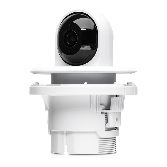
- Page 1 UniFi Video Camera G3 Flex Ceiling Mount Accessory Model: UVC-G3-F-C...
-
Page 2: Package Contents
Package Contents Ceiling Mount Ceiling Backing Mounting Bracket Plate Cover Installation Screw Screws Screw Anchors (Qty. 3) (Qty. 3) Installation Requirements • UVC G3 Flex (sold separately) • Refer to the UVC-G3-FLEX Quick Start Guide for camera installation instructions • Phillips screwdriver •... -
Page 3: Hardware Overview
Hardware Overview Ceiling Backing Plate Ceiling Mount Bracket Ceiling Mount Cover Note: Use of the Ceiling Backing Plate is optional depending on the installation type. -
Page 4: Before You Begin
Before You Begin 1. Disassemble the separate pieces of the ceiling accessory: a. Push in the two side clips of the Ceiling Backing Plate to release the backing plate from the Ceiling Mount Bracket. b. Pull the Mounting Cover off of the Ceiling Mount Bracket. -
Page 5: Hardware Installation
Hardware Installation The ceiling accessory can be installed in one of the following ceiling materials: Soft Ceiling • Use for installation on removable ceiling tiles where you have rear access to the Ceiling Mount Bracket. • Hard Ceiling Use for installation on hard lid ceilings where there is no rear access to the Ceiling Mount Bracket. - Page 6 Soft Ceiling Installation 1. Remove the ceiling tile. 2. Cut a 2 ¼-inch (57 mm) opening in the ceiling tile. 3. Place the Ceiling Mount Bracket through the opening in the ceiling. Note: Ensure that the arrows on the Ceiling Mount Bracket point in the direction the camera will face.
- Page 7 5. Connect one end of the Ethernet cable to the Ethernet port on the camera and the other end to a PoE 802.3af-compliant switch or compatible PoE adapter. 6. Align the notches on the camera with the tabs on the Ceiling Mount Bracket.
- Page 8 7. Use a Phillips screwdriver to install the included Installation Screw through the Ceiling Mount Bracket and into the base of the camera. 8. Proceed to the Mounting Cover Installation section.
-
Page 9: Hard Ceiling Installation
Hard Ceiling Installation 1. Align the notches on the camera with the tabs on the Ceiling Mount Bracket. Slide the camera into the Ceiling Mount Bracket, locking into place. 2. Use a Phillips screwdriver to install the included Installation Screw through the Ceiling Mount Bracket and into the base of the camera. - Page 10 3. Cut a 2 ¼-inch (57 mm) opening in the ceiling and pull an Ethernet cable though the opening. 4. Connect one end of the Ethernet cable to the Ethernet port on the camera and the other end to a PoE 802.3af-compliant switch or compatible PoE adapter.
- Page 11 5. Place the Ceiling Mounting Bracket through the opening in the ceiling. Note: Ensure that the arrows on the Ceiling Mount Bracket point in the direction the camera will face. 6. Use the three Screws to secure the Ceiling Mount Bracket to the ceiling.
- Page 12 Drywall Ceiling Installation 1. Cut a 2 ¼-inch (57 mm) opening in the ceiling. 2. Place the Ceiling Mount Bracket through the opening in the ceiling. Using the Ceiling Mount Bracket as a template, mark the three screw holes. Note: Ensure that the arrows on the Ceiling Mount Bracket point in the direction the camera will face.
- Page 13 5. Use a Phillips screwdriver to install the included Installation Screw through the Ceiling Mount Bracket and into the base of the camera. 6. Insert the three Screw Anchors into the three screw holes and then feed an Ethernet cable through the ceiling.
- Page 14 7. Connect one end of the Ethernet cable to the Ethernet port on the camera and the other end to a PoE 802.3af-compliant switch or compatible PoE adapter. 8. Align the Ceiling Mount Bracket with the Screw Anchors.
- Page 15 9. To secure the Ceiling Mount Bracket to the ceiling, insert the three Screws into the three screw holes and Screw Anchors.
- Page 16 Mounting Cover Installation Once the ceiling accessory and camera have been installed in the ceiling, follow the steps below to install the Mounting Cover: 1. Unlock the Mounting Cover by sliding the tab out. 2. Place the open Mounting Cover over the camera and Ceiling Mount Bracket.
-
Page 17: Limited Warranty
EU-conformiteitsverklaring kan worden geraadpleegd op het volgende internetadres: www.ui.com/compliance English Hereby, UBIQUITI declares that the radio equipment type UVC-G3-F-C is in compliance with Directive 2014/53/EU, 2014/30/EU & 2014/35/EU. The full text of the EU declaration of conformity is available at the following internet address: www.ui.com/compliance Eesti keel [Estonian] Käesolevaga deklareerib UBIQUITI, et käesolev raadioseadme tüüp UVC-G3-F-C... -
Page 18: Online Resources
Español [Spanish] Por la presente, UBIQUITI declara que el tipo de equipo radioeléctrico UVC-G3-F-C es conforme con la Directiva 2014/53/UE, 2014/30/UE & 2014/35/UE. El texto completo de la declaración UE de conformidad está disponible en la dirección Internet siguiente: www.ui.com/compliance Svenska [Swedish] Härmed försäkrar UBIQUITI att denna typ av radioutrustning UVC-G3-F-C...
Need help?
Do you have a question about the UniFi G3 Flex and is the answer not in the manual?
Questions and answers