Table of Contents
Advertisement
Advertisement
Table of Contents

Related Manuals for Ubiquiti UVC-G3-F-C


Summary of Contents for Ubiquiti UVC-G3-F-C
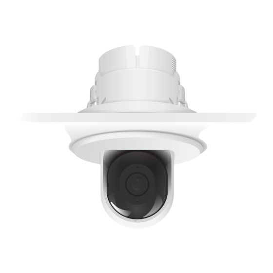
- Page 1 UniFi Video Camera G3 Flex Ceiling Mount Accessory Model: UVC-G3-F-C...
-
Page 2: Package Contents
Introduction Thank you for purchasing the Ubiquiti Networks® UniFi® Video Camera G3 Flex Ceiling Mount Accessory. This Quick Start Guide is designed to guide you through installation and includes warranty terms. Package Contents Ceiling Mount Ceiling Backing Mounting Bracket Plate Cover... -
Page 3: Hardware Overview
Hardware Overview Mounting Cover Ceiling Mount Bracket Ceiling Backing Plate Note: Use of the Ceiling Backing Plate is optional depending on the installation type. -
Page 4: Before You Begin
Before You Begin 1. Disassemble the separate pieces of the ceiling accessory: a. Push in the two side clips of the Ceiling Backing Plate to release the backing plate from the Ceiling Mount Bracket. b. Pull the Mounting Cover off of the Ceiling Mount Bracket. -
Page 5: Hardware Installation
Hardware Installation The ceiling accessory can be installed in one of the following ceiling materials: Soft Ceiling • Use for installation on removable ceiling tiles where you have rear access to the Ceiling Mount Bracket. • Hard Ceiling Use for installation on hard lid ceilings where there is no rear access to the Ceiling Mount Bracket. - Page 6 Soft Ceiling Installation 1. Remove the ceiling tile. 2. Cut a 2 ⅛-inch (53 mm) opening in the ceiling tile. 3. Place the Ceiling Mount Bracket through the opening in the ceiling. Note: Ensure that the arrows on the Ceiling Mount Bracket point in the direction the camera will face.
- Page 7 5. Connect one end of the Ethernet cable to the Ethernet port on the camera and the other end to a PoE 802.3af-compliant switch or compatible PoE adapter. 6. Align the notches on the camera with the tabs on the Ceiling Mount Bracket.
- Page 8 7. Use a Phillips screwdriver to install the included Security Screw through the Ceiling Mount Bracket and into the base of the camera. 8. Proceed to the Mounting Cover Installation section.
-
Page 9: Hard Ceiling Installation
Hard Ceiling Installation 1. Align the notches on the camera with the tabs on the Ceiling Mount Bracket. Slide the camera into the Ceiling Mount Bracket, locking into place. 2. Use a Phillips screwdriver to install the included Security Screw through the Ceiling Mount Bracket and into the base of the camera. - Page 10 3. Cut a 2 ⅛-inch (53 mm) opening in the ceiling and pull an Ethernet cable though the opening. 4. Connect one end of the Ethernet cable to the Ethernet port on the camera and the other end to a PoE 802.3af-compliant switch or compatible PoE adapter.
- Page 11 5. Place the Ceiling Mounting Bracket through the opening in the ceiling. Note: Ensure that the arrows on the Ceiling Mount Bracket point in the direction the camera will face. 6. Use the three Screws to secure the Ceiling Mount Bracket to the ceiling.
- Page 12 Drywall Ceiling Installation 1. Cut a 2 ⅛-inch (53 m) opening in the ceiling. 2. Place the Ceiling Mount Bracket through the opening in the ceiling. Using the Ceiling Mount Bracket as a template, mark the three screw holes. Note: Ensure that the arrows on the Ceiling Mount Bracket point in the direction the camera will face.
- Page 13 5. Use a Phillips screwdriver to install the included Security Screw through the Ceiling Mount Bracket and into the base of the camera. 6. Insert the three Screw Anchors into the three screw holes and then feed an Ethernet cable through the ceiling.
- Page 14 7. Connect one end of the Ethernet cable to the Ethernet port on the camera and the other end to a PoE 802.3af-compliant switch or compatible PoE adapter. 8. Align the Ceiling Mount Bracket with the Screw Anchors.
- Page 15 9. To secure the Ceiling Mount Bracket to the ceiling, insert the three Screws into the three screw holes and Screw Anchors. 10. Proceed to the Mounting Cover Installation section.
- Page 16 Mounting Cover Installation Once the ceiling accessory and camera have been installed in the ceiling, follow the steps below to install the Mounting Cover: 1. Unlock the Mounting Cover by sliding the tab out. 2. Place the open Mounting Cover over the camera and Ceiling Mount Bracket.
-
Page 17: Limited Warranty
(VI) has no original Ubiquiti MAC label, or is missing any other original Ubiquiti label(s); or (VII) has not been received by Ubiquiti within 30 days of issuance of the RMA. -
Page 18: Limitation Of Liability
SUBJECT TO LIMITATIONS, INTERRUPTIONS, DELAYS, CANCELLATIONS AND OTHER PROBLEMS INHERENT IN THE USE OF COMMUNICATIONS FACILITIES. UBIQUITI NETWORKS, ITS AFFILIATES AND ITS AND THEIR THIRD PARTY PROVIDERS ARE NOT RESPONSIBLE FOR ANY INTERRUPTIONS, DELAYS, CANCELLATIONS, DELIVERY FAILURES, DATA LOSS, CONTENT CORRUPTION, PACKET LOSS, OR OTHER DAMAGE RESULTING FROM ANY OF THE FOREGOING. -
Page 19: Declaration Of Conformity
Français [French] Le soussigné, UBIQUITI NETWORKS, déclare que l’équipement radioélectrique du type UVC-G3-F-C est conforme à la directive 2014/53/UE. Le texte complet de la déclaration UE de conformité est disponible à l’adresse internet suivante: www.ubnt.com/compliance Deutsch [German] Hiermit erklärt UBIQUITI NETWORKS, dass der Funkanlagentyp UVC-G3-F-C der... -
Page 20: Online Resources
Español [Spanish] Por la presente, UBIQUITI NETWORKS declara que el tipo de equipo radioeléctrico UVC-G3-F-C es conforme con la Directiva 2014/53/UE. El texto completo de la declaración UE de conformidad está disponible en la dirección Internet siguiente: www.ubnt.com/compliance Svenska [Swedish] Härmed försäkrar UBIQUITI NETWORKS att denna typ av radioutrustning...
Need help?
Do you have a question about the UVC-G3-F-C and is the answer not in the manual?
Questions and answers