Ubiquiti UVC-G3-FLEX Quick Start Manual
1080p indoor/outdoor ip camera with
infrared and 802.3af support
Hide thumbs
Also See for UVC-G3-FLEX:
- Quick start manual (27 pages) ,
- Quick start manual (21 pages) ,
- Quick start manual (19 pages)

Related Manuals for Ubiquiti UVC-G3-FLEX


Summary of Contents for Ubiquiti UVC-G3-FLEX
- Page 1 1080p Indoor/Outdoor IP Camera with Infrared and 802.3af Support Model: UVC-G3-FLEX...
-
Page 2: Package Contents
Introduction Thank you for purchasing the Ubiquiti Networks® UniFi® Video Camera G3 Flex. This Quick Start Guide is designed to guide you through installation and includes warranty terms. Package Contents G3 Flex Camera Indoor Mount Pole Mount Outdoor Cover Security Screw... -
Page 3: Outdoor Installation Requirements
• Surge protection should be used for all outdoor installations. We recommend that you use two Ethernet Surge Protectors, model ETH-SP-G2, one near the UVC-G3-Flex and the other at the entry point to the building. The ETH‑SP‑G2 will absorb power surges and safely discharge them into the ground. -
Page 4: Before You Begin
Before You Begin The UVC G3 Flex camera is designed to work with the UniFi Video® controller software (v3.9.2 or higher). The software may be hosted on any of the following: • UniFi Application Server, model UAS‑XG • UniFi NVR, model UVC-NVR-2TB •... -
Page 5: Hardware Overview
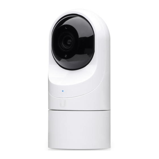
Hardware Overview Microphone Camera Lens Light Sensor Swivel Base Microphone Microphone for recording audio Camera Lens Lens for viewing/recording video Light Sensor Sensor for ambient light Status indicator for the following: LED State Status Alternating Device is busy; do not touch or unplug it. White/Blue This usually indicates that a process such as a firmware upgrade is taking place. -
Page 6: Bottom View
Bottom View Ethernet Port Reset Button Ethernet Port The Ethernet Port is a 10/100 Mbps port used to supply power from a PoE 802.3af‑compliant switch to the camera. The switch should be connected to a LAN running DHCP services and the UniFi Video Controller software. Reset Button The Reset Button is used to reset the camera to factory defaults. - Page 7 Desktop 1. Remove the Indoor Mount from the bottom of the camera. 2. Insert one end of the RJ‑45 cable into the Ethernet Port and the other end into a PoE 802.3af‑compliant switch. 3. Replace the Indoor Mount by lining up the notches with the slots on the camera base and pressing it down.
- Page 8 4. Place the camera on any flat surface and adjust the viewing angle by: • Tilting the lens up or down for vertical adjustment • Turning the base left or right for horizontal adjustment Wall 1. If the Ethernet cable is coming from the inside of a wall: a.
- Page 9 3. Connect the Ethernet cable to the Ethernet Port on the camera. 4. Attach the camera to the Indoor Mount by lining up the notches with the slots on the bottom of the camera. Press firmly until the camera snaps on. Vertical Mounting Horizontal Mounting Pole...
- Page 10 2. Connect an Ethernet cable to the Ethernet Port on the G3 Flex camera. Note: If you are mounting the camera outdoors, it must be installed in the upright position to prevent water from getting into the base of the camera. Use the Outdoor Cover for additional protection from moisture.
- Page 11 3. Attach the camera to the Pole Mount by: a. Pressing the camera against the Pole Mount and lining up the notches with the slots on the bottom of the camera. b. Slide the camera down onto the Pole Mount until it snaps into place.
- Page 12 5. Adjust the camera to the desired viewing angle by: • Tilting the lens up or down for vertical adjustment • Turning the base left or right for horizontal adjustment Installation is complete.
- Page 13 UniFi Video Ensure that you are running UniFi Video software version 3.9.2 or newer. The latest version of the UniFi Video software is available at www.ubnt.com/download/unifivideo The UniFi Video auto-management feature should automatically detect your new camera(s). To manage the camera, perform the following steps: 1.
-
Page 14: Specifications
Specifications UVC-G3-FLEX Ø 107.5 x 48 x 48 mm Dimensions (Ø 4.23 x 1.89 x 1.89") Weight 170 g (5.99 oz) Sensor 1/2.7" 2‑Megapixel HDR Sensor Lens EFL 3.4mm / f1.2 Viewing Angle with Lens Distortion Correction (LDC) LDC Off 87.4°... -
Page 15: Safety Notices
Safety Notices Read, follow, and keep these instructions. Heed all warnings. Only use attachments/accessories specified by the manufacturer. WARNING: Hot Surface. Do not touch. WARNING: Do not use this product in a location that can be submerged by water. WARNING: Avoid using this product during an electrical storm. -
Page 16: Limited Warranty
(VI) has no original Ubiquiti MAC label, or is missing any other original Ubiquiti label(s); or (VII) has not been received by Ubiquiti within 30 days of issuance of the RMA. -
Page 17: Limitation Of Liability
SUBJECT TO LIMITATIONS, INTERRUPTIONS, DELAYS, CANCELLATIONS AND OTHER PROBLEMS INHERENT IN THE USE OF COMMUNICATIONS FACILITIES. UBIQUITI NETWORKS, ITS AFFILIATES AND ITS AND THEIR THIRD PARTY PROVIDERS ARE NOT RESPONSIBLE FOR ANY INTERRUPTIONS, DELAYS, CANCELLATIONS, DELIVERY FAILURES, DATA LOSS, CONTENT CORRUPTION, PACKET LOSS, OR OTHER DAMAGE RESULTING FROM ANY OF THE FOREGOING. -
Page 18: Industry Canada
Note Some countries, states and provinces do not allow exclusions of implied warranties or conditions, so the above exclusion may not apply to you. You may have other rights that vary from country to country, state to state, or province to province. Some countries, states and provinces do not allow the exclusion or limitation of liability for incidental or consequential damages, so the above limitation may not apply to you. -
Page 19: Rohs/Weee Compliance Statement
CE Marking CE marking on this product represents the product is in compliance with all directives that are applicable to it. RoHS/WEEE Compliance Statement English European Directive 2012/19/EU requires that the equipment bearing this symbol on the product and/or its packaging must not be disposed of with unsorted municipal waste. - Page 20 Español La Directiva 2012/19/UE exige que los equipos que lleven este símbolo en el propio aparato y/o en su embalaje no deben eliminarse junto con otros residuos urbanos no seleccionados. El símbolo indica que el producto en cuestión debe separarse de los residuos domésticos convencionales con vistas a su eliminación.
-
Page 21: Declaration Of Conformity
Français [French] Le soussigné, UBIQUITI NETWORKS, déclare que l’équipement radioélectrique du type UVC-G3-FLEX est conforme à la directive 2014/53/UE. Le texte complet de la déclaration UE de conformité est disponible à l’adresse internet suivante: www.ubnt.com/compliance Deutsch [German] Hiermit erklärt UBIQUITI NETWORKS, dass der Funkanlagentyp UVC-G3-FLEX der... -
Page 22: Online Resources
Português [Portuguese] O(a) abaixo assinado(a) UBIQUITI NETWORKS declara que o presente tipo de equipamento de rádio UVC-G3-FLEX está em conformidade com a Diretiva 2014/53/UE. O texto integral da declaração de conformidade está disponível no seguinte endereço de Internet: www.ubnt.com/compliance Română... - Page 23 . u b n t . c o m ©2018 Ubiquiti Networks, Inc. All rights reserved. Ubiquiti, Ubiquiti Networks, the Ubiquiti U logo, the Ubiquiti beam logo, and UniFi Video are trademarks or registered trademarks of Ubiquiti Networks, Inc. in the United States and in other countries.
Need help?
Do you have a question about the UVC-G3-FLEX and is the answer not in the manual?
Questions and answers