
Related Manuals for Inovance AM600 Series


Summary of Contents for Inovance AM600 Series
- Page 1 User Guide AM600 Series PLC (NPN) Suzhou Inovance Technology Co,.Ltd Address: No.16 Youxiang Road, Yuexi, Wuzhong District, Suzhou 215104 Customer service hotline: 4000-300124 Website: http://www.inovance.com *19011279A01* 19011279A01...
-
Page 2: Safety Instructions
This guide mainly describes the specifications, characteristics, and usage of the AM600 series PLC. Read this guide carefully before using to fully understand the product and ensure safety. Visit our website (www.inovance.com) for the latest version of the guide. - Page 3 During control system design ◆ Provide a safety circuit outside the PLC so that the control system can still work safely once external power failure or PLC fault occurs. ◆ Add a fuse or circuit breaker because the module may smoke or catch fire due to long-time overcurrent caused by operation above rated current or load short-circuit.
- Page 4 ◆ Prevent metal filings and wire ends from dropping into The ventilation holes of the PLC during installation. Otherwise it may result in fire, fault and malfunction. ◆ Ensure there are no foreign matters on ventilation surface. Failure to comply may result in poor ventilation, which may cause fire, fault and malfunction.
- Page 5 Operation and Maintenance ◆ Maintenance & inspection must be carried out by personnel who have the necessary electrical training and experience. ◆ Do not touch the terminals while the power is on. Failure to comply may result in electric shock or malfunction. ◆...
-
Page 6: Product Information
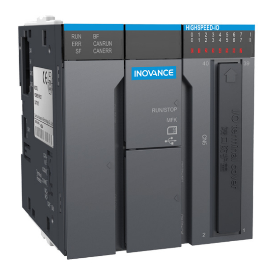
2 Product Information 2.1 Model Number and Nameplate Model Category Description 10 M program storage space; 20 M data storage space; 2 RS485 ports, 1 CANopen/CANlink port, and AM600-CPU1608TN CPU module 1 LAN port; Support for EtherCAT bus; built-in 16-in-8-out high-speed IO;... - Page 7 2.2 External Interface Figure 1 Diagram of CPU module interfaces Interface Name Function DB9 (CN1)/(receptacle) 2 RS485 ports, supporting MODBUS protocol DB9 (CN2)/(receptacle) 1 CANopen/CANlink port Network port (CN4) EtherCAT protocol 1. MODBUS TCP protocol 2. Standard Ethernet functions Network port (CN3) 3.
-
Page 8: General Specifications
Interface Name Function Program download and commissioning 16-point high-speed input High-speed IO 8-point high-speed output I/O indicator Indicates the signal effectiveness of all I/Os DIP switch RUN/STOP DIP switch SD card interface Stores user programs and user data MFK key Multi-functional key Operation indicator (RUN) CPU module error indicator (ERR) - Page 9 Item Specifications Flash space for power 512 KB failure memory SD card capacity Up to 32 G Program power failure Flash or SD card retention (only available when power memory is on for more than 35s before going out) Internal 5 V power 1500 mA (rated value) output current 8-point input interrupt (CPU module high-speed DI),...
-
Page 10: Terminal Layout
■ Output Item Specifications Signal Name Output (Y0-Y7) Output polarity Sink Voltage of the control 5 VDC–24 VDC circuit Rated load current 0.1 A/point, 0.5 A/COM Max. voltage drop at ON 0.2 V (typical) Leakage current at OFF Less than 0.1 mA 200 kHz (an external equivalent load above 12 mA is Output frequency required) - Page 11 * 1 The CPU module provides 16 high-speed inputs. The first 4 support 24 V single-ended input or 5 V differential input, and the other 12 support 24 V single- ended input.
-
Page 12: Wiring Precautions
* 2 For specific wiring methods and wiring examples, contact Inovance for a High- Speed I/O Wiring User Guide. ■ Equivalent internal circuit: 3.3k Xn2-24V Xn2-DIFF Xn2-COM 3.3k 3.3k 3.2 Wiring Precautions 1) The total length of the high-speed I/O cables should be within 3.0 m. - Page 13 Example Wiring (2) NPN 24 V level input Differential 5 V level input 4 Mechanical Design Reference 4.1 Dimensions 80.0 95.0 AM600-CPU1608TN 0 1 2 3 4 5 6 7 CANRUN CANERR RUN/STOP Figure 3 Dimensions of CPU module (in mm)
-
Page 14: Communication Connection
5 Communication Connection 5.1 Cabling of CPU module and communication module 1) RJ45 cable connection ● Insert the cable connector into the RJ45 port of the communication module until you hear a click sound. Figure 4 Cable connection diagram ● Removal: press the release tab of the connector to pull out the connector and module horizontally. - Page 15 POWER Risk o -ECT POWER EtherCAT Risk of c shock Figure 5 Fix the cable end that near the device 5.2 EtherCAT bus connection 1) EtherCAT Bus Specifications Item Specifications Communication EtherCAT protocol protocol Service supported CoE (PDO, SDO) Max. synchronous 120 us (typical) jitter Synchronization...
- Page 16 Up to 125 slaves. AM401: supports 4 DSP402 slaves; AM402: Number of slaves supports 8 DSP402 slaves EtherCAT frame 44–1498 bytes length Process data Max. 1486 bytes per Ethernet frame 2) Wiring The CPU module provides a CN4 port for EtherCAT bus communication. An ECT communication network cable that meets the following requirements is a must: Figure 6 Requirements on the EtherCAT cable ■...
- Page 17 Item Specifications Cable type Flexible crossover cable, S-FTP, Cat 5e EIA/TIA568A, EN50173, ISO/IEC11801 Complied standards: EIA/TI Abulletin TSB, EIA/TIA SB40-A&TSB36 Conductor type Twisted pair Pair 5.3 Connection through CANopen/CANlink bus 1) Networking diagram CAN bus topology is shown below. Using shielded twisted cables to connect CAN bus is recommended.
- Page 18 AM600-CPU1608TN CANRUN CANERR RUN STOP Figure 8 CANopen terminal on CPU module 3) Wiring CANopen requires a DB9 connector for data transmission. DB9 connector pins are defined as follows: Diagram Definition of signal PIN2 CANL PIN7 CANH PIN3 Use shielded twisted pair cable to connect CAN bus, and attach a 120 Ω termination resistor to each end of the bus to prevent signal reflection.
- Page 19 AM600-CPU1608TN CANRUN CANERR RUN STOP Figure 9 RS485 communication terminal on CPU module Pin definition: Channel Definition Function RS485- COM0 RS485 differential pair negative signal COM0 (RS485) RS485+ COM0 RS485 differential pair positive signal GND0 COM0 power GND RS485- COM1 RS485 differential pair negative signal COM1 (RS485) RS485+ COM1 RS485 differential pair positive signal...
-
Page 20: Programming Tool
6 Programming Tool 6.1 Programming tool download Inovance provides InoPro as the user programming tool for AM600 series medium-sized PLCs. It is free and you can obtain a DVD copy from our distributors or download it from our website www.inovance.com, where you can also download documents about AM600 series PLC products and their applications. -
Page 21: Operation And Maintenance
Hardware requirements: A desktop PC or a laptop running Windows XP or above, with 2 GB RAM and more than 5 GB free space on the hard disk or SSD. To ensure performance, the CPU frequency should be above 2 GHz. The PC can be connected with the PLC through a LAN cable. - Page 22 8 Indicators and MFK Key 8.1 CPU module indicator Name Indication Indicates the status of the system (running or RUN indicator stopped). The indicator is on during operation and off when the system is stopped ERR indicator Indicates system failure SF indicator Expansion bus error indicator BF indicator...
- Page 23 screen will display information as follows: Fault information on LED screen and remedies: CPU and I/O Indication Remedy Module No fault CPU model does not agree with software. Check that Contact your distributor the PLC is authorized. CPU Local expansion bus Check the connection between error local rack modules.
- Page 24 Check the detailed fault ModBus COM0 error information in the software. Check the detailed fault ModBusTcp error information in the software. CANopen Indication Remedy Check the connection between Slave error slave rack modules. Check that the configuration of the Slave hardware slave rack module is consistent configuration error with that in the software.
-
Page 25: Module Connection
9 Module Connection 9.1 Connection between Power Supply, CPU and Expansion Modules The connection between the modules is mainly through the connection interfaces and latch of each module. The following example instructs how to connect the CPU module to the power module. 1. - Page 26 Note: After the I/O terminal block is mounted to CN5, fix it with a torque of 0.2–0.25 N•m, as shown in the following figure. 9.2 Connection between Power Supply, CPU and Expansion Modules 1. Pull down all the DIN rail mounting hooks on the back of the module (as shown in the following figure).
- Page 27 2. In direction A as shown in the following figure, hang the clasp on the upper part of the module onto the top of the DIN rail, and press the module assembly firmly in direction B until it fully engages with the guide rail. 3.
-
Page 28: Warranty Agreement
5) Damage out of the equipment (for example, external device factors) The maintenance fee is charged according to the latest Maintenance Price List of Inovance. If there is any problem during the service, contact Inovance's agent or Inovance directly. Inovance reserves the rights for explanation of this agreement.
Need help?
Do you have a question about the AM600 Series and is the answer not in the manual?
Questions and answers