Advertisement
Quick Links
Advertisement

Subscribe to Our Youtube Channel
Related Manuals for Delta M81 Series


Summary of Contents for Delta M81 Series
- Page 2 If you need technical assistance, our technical support engineers will be glad to assist you with all technical difficulties, you can reach them by dialing our toll-free service and technical support number : 1-877-DELTA-2K/1-877-335-8225 (USA / CANADA Only ). Not only you will get to speak with our experience technical support team, we also provide web-site address (http://pc.delta.com.tw), prod-...
-
Page 3: Table Of Contents
CONTENTS 1. Checklist.............2 2. Introduction............3 3. Specification............4 4. Layout Guide............6 5. Function Illustrations........8 6. Hardware Installation........20 7. BIOS Configuration .......... 25 8. Software Installation ........52 P/N : 5011501201 AUG/1999 REV1.1... -
Page 4: Checklist
1. Checklist Check that your package is complete. If any listed items are missing, please contact your retailer immediately. The M81-MX series motherboard package contains the following. Package box M81-MX Series Motherboard Anti-static bag ! ! ! ! ! EPE sheet... -
Page 5: Introduction
2. Introduction 2. Introduction The M81-MX series motherboard offers one of the highest performance solutions on the powerful Intel PPGA370 processor. The motherboard uses the Intel i810 series chipset which includes the FW82810/82810DC100 (North Bridge), FW82801AA/82801AB (South Bridge) and N82802AB (Firmware Hub) chip in the Micro ATX form factor. The principal feature of this motherboard is it can support PPGA370 Celeron processor which is close to Pentium º... -
Page 6: Specification
3. Specification Chipset M81L-MX Consists of the Intel’s FW82810 + FW82801AB M81-MX Consists of the Intel’s FW82810 + FW82801AA M81DC-MX Consists of the Intel’s FW82810DC100 + FW82801AA Winbond’s W83627HF LPC Super I/O AC97 Codec CPU Support Intel’s PPGA370 Celeron Processors System Bus Frequency 66/100MHz System Bus Frequency Supported System Bus Frequency and CPU core voltage auto-detected... - Page 7 3. Specification Integrated Consumer IR and Standard IR supports (This item is optional) Dual Universal Serial Bus Ports Dual PS/2 mini DIN supports Keyboard and Mouse Integrated 3D/2D AGP Graphics Controller Single Game_Audio/Line-in/Line-out/MIC Ports Hardware Monitor Functions OnNow Functions Power Management Functions Built-in PCI 3D audio compliant with PC99, Intel AC97 and AMR v1.01 Power Harris HIP6021 PWM Power Controller...
-
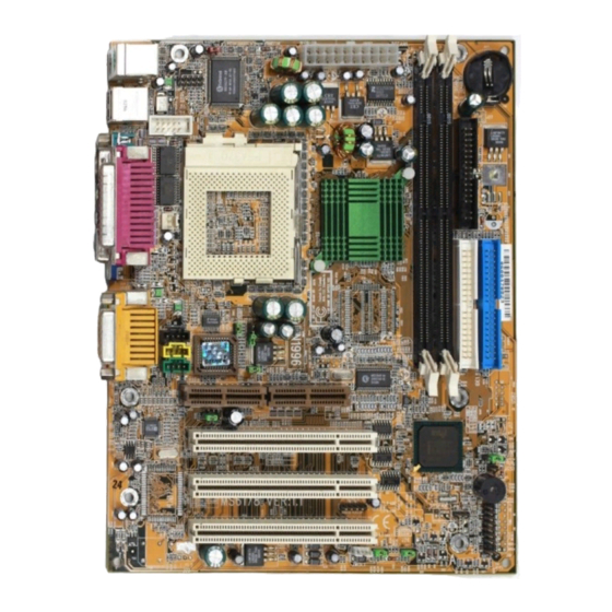
Page 8: Layout Guide
4. Layout Guide Use the following illustration and key to identify the components on your motherboard. & & & & & ' ' ' ' $ $ $ $ % % % % # # # # "... - Page 9 4. Layout Guide & & & & & IrDA compliant IR infrared Header (This item is optional) Chassis Fan Connector ' ' ' ' ' Flash BIOS Lock Header (This item is optional) Buzzer Lithium CR2032 Battery Front Panel I/O Header "...
-
Page 10: Function Illustrations
5. Function Illustrations Refer to this section for details on the hardware configuration. All jumper settings should be configured prior to install the motherboard. 5.1. Processor socket “PGA370” PGA370 socket is a 370-Pin ZIF socket that can install the PPGA370 Celeron Processors. 5.2. - Page 11 5. Function Illustrations For best performance, we recommend to use PC-100 DIMM module on the motherboard. If you install more than one module, the module should have different capacities, but the memory chips should be the same type. 5.3. PCI slot “PCI1,2,3,” It is a 120-Pin 32-bit expansion slot that accommodate all PCI peripherals and meet the PCI v2.2 specifications.
- Page 12 5.4. Audio Modem Riser Slot “AMR” It is a 46-Pin expansion slot that accommodate a specially designed Audio Modem Riser card called an AMR. Main processing is done through software and controller by motherboard’s I/O Controller Hub. This provides an upgrade able audio/modem solution at an incredibly low cost. Note : Follow the steps mentioned below to install a AMR card.
- Page 13 5. Function Illustrations 5.6. IDE Devices Header “IDE1,2” It is a 40-Pin box header that support standard ATAPI IDE devices. This is an dual channel IDE controller, a primary and a secondary. Each channel may support up to two ATAPI IDE devices. The primary channel has priority to the secondary channel.
- Page 14 5.7. Serial Port Header “COM2” It is a 10-Pin box header that used for serial devices such as a mouse, fax/modem and so on. This serial port is identified by the system as COM2/4. 5.8. Front Panel I/O Header “FSP1” The M81-MX series motherboard connectors to the front panel I/O are located on jumper block FSP1.
- Page 15 5. Function Illustrations Key Lock - It is a 2-Pin header connects to the chassis-mounted key lock switch. The key lock switch is used to lock the keyboard for security purpose. Power LED - It is a 3-Pin header connects to the chassis-mounted power LED. Power LED is on when the motherboard is supplied power.
- Page 16 5.10. Buzzer “BZ1” It is a 5 volts onboard buzzer. When system has any abnormally state that you will hear warnings through buzzer. 5.11. Power / CPU / Chassis Fan Connector “J1,J2,J10” These are 3-Pin connector that support cooling fan of 12 VDC/0.5A or less, when the system goes into sleep state, fan should be shut down to eliminate audible noise and reduce power consumption.
- Page 17 5. Function Illustrations 5.12. IrDA compliant IR Infrared Header “J11” ( This item is optional ) It is a 10-Pin Standard IR(SIR) and Consumer IR(CIR) headers. That support an optional wireless transmitting and receiving infrared module. This module mounts to a small opening on system case that support this feature.
- Page 18 5.14. CMOS Memory Clear Header “JP1” It is a 3-Pin header that if your system can not boot-up because you forgot your password or the CMOS setting need to be reset to default values after the system BIOS has been updated. The following instructions can be performed to clear the CMOS and password.
- Page 19 5. Function Illustrations Jumper Cap Function Open Pin 1-2 Lock Flash BIOS Short Pin 1-2 Unlock Flash BIOS 5.16. CD-In Header “J6,J7” CD-in J7 is a 4-Pin 2.54mm audio header which can be used to input the audio from a CD-ROM or DVD drive. CD-in J6 4-Pin 2.0mm header is exactly the same, except that it support an alternative kind of connector.
- Page 20 Assignment Assignment +3.3V +3.3V -12V +3.3V PW ON/OFF PW-GOOd +5VSB +12V 5.18. Back Panel I/O Connectors “PS/2, USB, LPT, COM1, VGA1, Game_Audio” The back panel provides external access to PS/2 style Keyboard and Mouse port, one Serial port, one AGP display port, one Parallel port, dual USB port and one Game_Audio port, which are integrated on the motherboard for PC99 specification.
- Page 21 5. Function Illustrations Game Port PS/2 Mouse PS/2 Keyboard VGA1 Line-Out COM1 Line-In M81-MX Series User’s Manual...
-
Page 22: Hardware Installation
6. Hardware Installation 6.1 Before you Begin The M81-MX series motherboard is designed to fit into a standard Micro ATX form factor chassis. The pattern of the mounting holes and the position of back panel I/O ports meet the Micro ATX motherboard specification. The chassis may come with various mounting fasteners which are made of metal or plastic. - Page 23 6. Hardware Installation Turn the swivel to locking position and hook it under the latch on the side of the socket to lock it in place. Orient the cooling fan and heat-sink then insert firmly. Locate the power connector J1 for the processor cooling fan, then connect the cable from cooling fan to J1.
- Page 24 Step4: Install IDE Device drive Locate the IDE1 and IDE2 box header on the motherboard. IDE1-Connect one end of the 40-Pin ribbon cable that comes with the drive to the HDD header, and the other end of the cable to the IDE1 box header on the motherboard.
- Page 25 6. Hardware Installation The primary channel has priority to the secondary channel. Within each channel, the two different devices are distinguished by master and slave relationship. The master device has priority over the slave device. (Refer to illustration on the below) Primary IDE1 Secondary IDE2...
- Page 26 Step6: Front Panel I/O Connectons Follow the instruction carefully for proper connections to your front panel display and control. Power SW Reset SW HDD LED Power LED Key Lock (If you have a speaker on the chassis that we recommend not to use them because it will have buzzer noise when the system is booted.) Step7: ATX1 / HDD / FDD Power Connection Connect ATXPWR of the power supply unit to the ATX1 connector on the...
-
Page 27: Bios Configuration
7. BIOS Configuration 7. BIOS Configuration The motherboard provides a 4MB, 3.3V, 32-Pin PLCC package Firmware Hub chips that can be updated using provided BIOS Utility. The Setup Utility stores data about motherboard com- ponents and the configuration of devices that are connected to it. The information is used to test and initialize components at start up time and to make sure everything runs properly when the system is operating. - Page 28 At the bottom of the setup screen you will notice a legend bar. The keys in the legend bar allow you to navigate through the various setup menus. The following table lists shown you the keys found in the legend bar with their corresponding alternates and functions. Navigation Key(s) Function Description <F1>...
- Page 29 7. BIOS Configuration 7.1 Standard CMOS Features Selecting “Standard CMOS Features” on the main program screen display this menu : User configured fields appear in a different color. If you need information on selected field, Press the <F1> key. The help menu will appear to provide you with the information you need.
- Page 30 7.1.2 IDE HDD Disks [Auto] Selecting “IDE Primary Master” on the Standard CMOS Features screen display this menu: Press <Enter> key to automatically detect an IDE hard disk drive. If automatic detection is successful, the correct values will be filled in the remaining fields on this screen. Displayed up are explanation of the Maxtor Diamond 5.7GB HDD.
- Page 31 7. BIOS Configuration hard disk drive must be partitioned (such as with FDISK.EXE), please refer to a MS-DOS manual and then formatted before data can be read from and write on Primary IDE hard disk drive must have its partition set to active (also possible with FDISK.EXE).
- Page 32 [All Errors] : Whenever the BIOS detects a non-fatal error the system will be stopped. [No Errors] : The system boot will not stop for any error that may be detected and you will be prompted. The available options for Halt On are : [All, But Keyboard] [All, But Diskette] [All, But Disk/Key] [All Errors] [No Errors].
- Page 33 7. BIOS Configuration 7.2 Advanced BIOS Features Selecting “Advanced BIOS Features” on the main program screen display this menu : This feature allows you to set the various system options of your choice, including virus warning, external cache, security option and boot operations. To access the Advanced BIOS Features screen, highlight this option on the main menu screen and press <Enter>...
- Page 34 When this item is enabled, it allows the system to carry out cache memory error checking if the cache memory chips support ECC (Error Checking and Correction). The available options for CPU L2 Cache ECC Checking are : [Enabled] [Disabled]. 7.2.4 Processor Number Feature [Disabled] If you have installed Pentium III Processor on the motherboard and enabled this item.
- Page 35 7. BIOS Configuration 7.2.11 Typematic Rate Setting [Disabled] Typematic Rate (Chars/Sec) [6] Typematic Delay (Msce) [250] This setting allows you to select which key strokes repeat at a rate determined by the keyboard controller. When Enabled , the typematic rate and typematic delay can be selected.
- Page 36 7.3 Advanced Chipset Features Selecting “Advanced Chipset Features” on the main program screen display this menu : To access the Advanced Chipset Features screen that define critical timing parameters of the motherboard components. Generally, you should leave the item on this feature at their default values unless you are very familiar with the technical specification of your system hardware.
- Page 37 7. BIOS Configuration 7.3.3 System BIOS Cacheable [Enabled] Video BIOS Cacheable [Enabled] These items allow the System BIOS and Video BIOS to be cached in memory for faster performance. We recommend that you leave these item at the default values. The available options for System and Video BIOS Cacheable are : [Enabled] [Disabled].
- Page 38 7.4 Integrated Peripherals Selecting “Integrated Peripherals” on the main program screen display this menu : This option displays a list of items which defines the operation of some. Peripheral items on the systems input/output ports. To access the Integrated Peripherals screen, highlight this option on the main menu screen and press <Enter>...
- Page 39 7. BIOS Configuration IDE Primary Master/Slave PIO and IDE Secondary Master/Slave PIO these four items let you assign which kind of PIO (Programmed Input/Output) is used by IDE devices. You can choose Auto, to let the system auto detect which PIO mode is best, or you can install a PIO mode from 0-4.
- Page 40 The POWER ON Function item allows you to power on the system by pressing hot keys or typing a password. Refer to explain in the below. [Password] : Disable the function of power button and let the system can only be powered on through the preset keys (like a password).
- Page 41 7. BIOS Configuration Use IR Pins [IR-Rx2Tx2] The IrDA is Hewlett Packard infrared communication protocol with maximum baud rate up to 115.2K bps, and the ASKIR is Sharp infrared communication protocol with maximum baud rate up to 57.6K bps. The UART2 Mode Setting depends on which type of infrared module is used in the system.
- Page 42 The available options for Parallel Port Mode are : [SPP] [EPP ] [ECP] [ECP+EPP]. The available options for EPP Mode Select are : [EPP1.7] [EPP1.9]. The available options for ECP Mode Use DMA are : [3] [1]. 7.4.11 PWRON After PWR-Fail [Off] A traditional ATX system should remain at power off stage when AC power re- sumes from power failure.
- Page 43 7. BIOS Configuration 7.5 Power Management Setup Selecting “Power Management Setup” on the main program screen display this menu : The Power Management Setup option controls the power management functions. This motherboard supports ACPI (Advanced Configuration and Power management Interface). The system has various power saving modes that allows the system to be automatically resumed by certain events.
- Page 44 and it will appear in exactly the same state as it was before it was suspended to RAM. The available options for ACPI Suspend Type are : [S1(POS)] [S3(STR)]. 7.5.3 Power Management [User Define] Suspend Mode [Disabled] HDD Power Down [Disabled] These items acts like a master switch for the power saving mode and hard disk timeout.
- Page 45 7. BIOS Configuration 7.5.6 Suspend Type [Stop Grant] You can set suspend mode by this item. [Stop Grant] : If Stop Grant is selected, the CPU clock will enter into sleep mode. [PwrOn Suspend] : If PwrOn Suspend is selected, the CPU will enter into doze mode.
- Page 46 The available options for Power On By Ring/LAN are : [Disabled] [Enabled]. 7.5.11 CUP Thermal-Throttling [50.0%] This option defines what percentage of time the system will halt the Processor clock when it is in power-saving mode. The available options for CPU Thermal-Throttling are : [50%] [37.5%] [25.0%] [12. 5%] [87.5%] [75%] [62.5%].
- Page 47 7. BIOS Configuration 7.6 PnP/PCI Configurations Selecting “PnP/PCI Configurations” on the main program screen display this menu : This option that configures how PnP and PCI expansion slots operate on the motherboard use system IRQs & DMAs. You must setup the IRQ and DMA assignment correctly through the PnP/PCI Configuration setup Utility, otherwise the motherboard will not work properly.
- Page 48 7.7 PC Health Status Selection “PC Health Status” on the main program screen display this menu : This option allows you to set CPU Warning Temperature on the motherboard, also display will list a series of items such as critical voltage and fan speeds. 7.7.1 CPU Warning Temperature [60 C/140 This item is used to set a CPU warning temperature.
- Page 49 7. BIOS Configuration 7.8 Frequency Control Selecting “Frequency Control” on the main program screen display this menu : The CPU Bus Clock and System Clock frequency will automatically be modulated which helps reducing electromagnetic interference. 7.8.1 CPU Clock/Spread Spectrum [Auto] This option sets the CPU Bus Clock/Spread Spectrum to Auto, system clock fre- quency will automatically be modulated which helps reducing electromagnetic interference.
- Page 50 7.9 Load Fail-Safe Defaults Selecting “Load Fail-Safe Defaults” on the main program screen and press <Enter> key on this option. You get a confirmation dialog box with a message display this menu : When you pressing “Y” key to load the BIOS default values for the most stable, minimal performance system operations.
- Page 51 7. BIOS Configuration 7.11 Set Supervisor / User Password You can set either Supervisor or User Password, or both of them. The differences between are: Supervisor Password : Can enter and change the options of the setup menus. User Password : Just can only enter but do not have the right to change the options of the setup menus.
- Page 52 Type the password, up to eight characters in length, and press <Enter> key. The pass- word typed now will clear any previously entered password from CMOS memory. It will be asked to confirm the password, Type the password again and press <Enter> key, or you may also press <ESC>...
- Page 53 7. BIOS Configuration 7.12 Save & Exit Setup/Exit Without Saving Selecting “Save & Exit Setup” on the main program screen and press <Enter> key on this option. You get a confirmation dialog box with a message display this menu : Pressing <Y>...
-
Page 54: Software Installation
8. Software Installation This installation guide is designed to install Driver and Utility software in Windows OS. We recommend that you read this section thoroughly before starting your installation. Although i810 series motherboard passed testing on several operating system, some folders are subdi- vided into different operating systems such as DOS, Windows 95/98/NT and so on. - Page 55 A per-warning message will pop up on the screen when the monitored parameters is out of the preset range. This software have to installed under Windows OS. Click “DELTA Hardware Doctor 3.5” on the Figure 3, the following screen will appear Figure 4.
- Page 56 Figure 6 Figure 7 Set threshold you want for system temperature, voltage and fan speed, by moving the slide bars or by clicking the increase/decrease buttons. 8.3 Intel 810 VGA For Win98 Installation Click “Intel 810 VGA Install” on the Figure 3” the following screen will appear Figure 8. Click “Intel 810 VGA For Win98”...
- Page 57 8. Software Installation Figure 10 After install is completed, you need to restart the system before you can activate the program. Reconfiguration under Windows 98 (Reconfiguring through the Device Manager). Click “Start” ÷ select “Settings” ÷ then click “Control Panel” the following screen will appear Figure 11.
- Page 58 Figure 13 Step 1 : Copy INF File to HD Click “Copy INF File to HD” the following screen will appear Figure 14. To continue install procedure and click Next ÷Click Yes the following screen will appear Figure 15 to install INF Files software program that default directory is C:\Program Files\Intel\IntelINF.
- Page 59 8. Software Installation Figure 16 Figure 17 After install is completed, you need to restart the system before you can activate the program. Reconfiguration under Windows 98 (Reconfiguring through the Device Manager). Click “Start”÷select “Settings”÷then select “Control Panel”, the following screen will appear Figure 11.
- Page 60 BIOS can be downloaded from the Web site : http://pc.delta.com.tw. The system BIOS is stored in a 4MB Firmware Hub chip which can be erased and repro- grammed by the BIOS Utility. There are two files in the BIOSTOOL directory.
- Page 61 : (1) this device may not cause harmful interference, and (2) this device must accept any interference received, including interference that may cause undesired operation. Responsible Party Name : DELTA PRODUCTS CORPORATION Address : 4405 CUSHING PARKWAY FREMONT.CA 94538, U.S.A.
- Page 62 EN 50082-1 / 1997 : EN61000-4-2/-3/-8, EN 50204 (Identification of regulations / standards) This declaration is the responsibility of the manufacturer / importer DELTA ELECTRONICS, INC. 11F-3, 266, 2ND WEN-HWA ROAD., SEC. 1, LINKOU, TAIPEI HSIEN, TAIWAN, R.O.C. (Name / Address)
Need help?
Do you have a question about the M81 Series and is the answer not in the manual?
Questions and answers