
Related Manuals for Federal Signal Corporation PAGASYS GEN II


Summary of Contents for Federal Signal Corporation PAGASYS GEN II
- Page 1 PAGASYS GEN II ® Remote Amplifier and Controller Models: GENII-RC and GENII-RA700 Description, Installation, and User Manual 25500654 Rev. A2 1021 Printed in U.S.A. © Copyright 2020-2021 Federal Signal Corporation...
- Page 2 A copy of this limited warranty can also be obtained by written request to Federal Signal Corporation, 2645 Federal Signal Drive, University Park, IL 60484, email to info@fedsig.com or call +1 708-534-3400.
-
Page 3: Table Of Contents
3.1 GENII-RC Features ..........................9 3.1.1 Audio ............................9 3.1.2 Digital I/O ..........................10 3.1.3 Access Panels ........................10 3.1.4 PAGASYS GEN II I/O Cards ....................10 3.1.5 PAGASYS GEN II Amplifiers ....................10 3.1.6 System Robustness ......................10 3.2 GENII-RC Specifications ........................10 3.2.1 GENII-RC Front panel ......................11 3.2.2 Rear Panel ..........................12... - Page 4 Figure 3 GENII-RC Rear Panel 16 Figure 4 GENII-RA700 Front Panel 18 Figure 5 GENII-RA700 Front Panel 20 Figure 6 GENII-RA700 Rear Panel AC Chassis 21 Figure 7 Standby Wiring 28 PAGASYS GEN II Remote Amplifier and Controller (GENII-RC and GENII-RA700) Federal Signal www.fedsig.com...
- Page 5 Tables Table 1 GENII-RC Audio 9 Table 2 GENII-RC Environmental and Physical Specifications 10 Table 3 GENII-RC Power Input, AC Model 10 Table 4 GENII-RC LED State Indications 11 Table 5 GENII-RC Inputs and Outputs 12 Table 6 GENII-RC System Faults 13 Table 7 GENII-RC Specifications 17 Table 8 RJ45 Connections 17 Table 9 GENII-RA700 Environmental and Physical Specifications 19...
-
Page 6: Safety Messages
Perform all work under the direction of the installation or service crew safety foreman. • Read and understand all instructions before installing, operating, or servicing this equipment. PAGASYS GEN II Remote Amplifier and Controller (GENII-RC and GENII-RA700) Federal Signal www.fedsig.com... - Page 7 Safety Messages • All effective warning sounds may, in certain circumstances, cause permanent hearing loss. Take appropriate precautions, such as wearing hearing protection. The maximum sound level exposure limits specified in OSHA 29 CFR 1910 should not be exceeded. • For optimum sound distribution, do not install the loudspeakers where objects would block any portion of the front of the system.
- Page 8 Pay careful attention to the notice located on the equipment. Read and understand the information contained in this manual before attempting to install or service the system. PAGASYS GEN II Remote Amplifier and Controller (GENII-RC and GENII-RA700) Federal Signal www.fedsig.com...
-
Page 9: General Description
In addition to built-in audio and I/O capabilities, it is fully compatible with all PAGASYS GEN II I/O boards and amplifiers and can be included in a PAGASYS GEN II networked system with other GENII-RCs and/or GEN II full controllers. -
Page 10: Digital I/O
Up to eight PAGASYS GEN II access panels and/or mic stations can be connected. 3 1 4 PAGASYS GEN II I/O Cards Any combination of up to 63 PAGASYS GEN II I/O cards can be connected to provide additional I/O, cabinet fan control and monitoring, and beacon control and monitoring. -
Page 11: Genii-Rc Front Panel
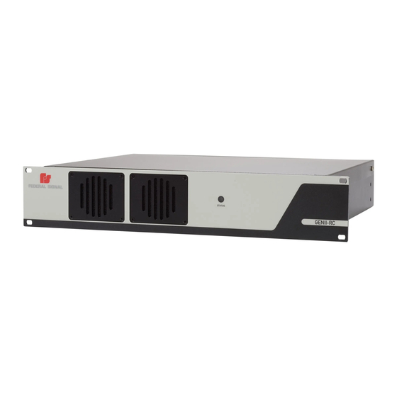
GENII-RC Remote Controller 3 2 1 GENII-RC Front panel Figure 1 GENII-RC Front Panel Two removable fan-filter covers LED indicator The GENII-RC controller has the following: • Two removable fan-filter covers • Replaceable filters: replacement filters can be purchased as a service part from Federal Signal •... -
Page 12: Rear Panel
I/O card power usage. RJ45 Amp interface port (1) • Max amplifiers: 128 GEN II amplifiers • Standby amp support: yes • ISMT support: optional, requires ISMT cards PAGASYS GEN II Remote Amplifier and Controller (GENII-RC and GENII-RA700) Federal Signal www.fedsig.com... -
Page 13: Genii-Rc System Faults
GENII-RC Remote Controller RJ45 Access Panel ports (8) • Each can be used for AP or as general-purpose audio input • Nominal audio input level: 0 dBu (0.775 V • For pinout, see “Table 8 RJ45 Connections” on page 17 RJ11 Fault relay contact (1) •... - Page 14 I/O board is reporting the rack is over- temperature. Pcp Node Id Mismatch An I/O board software address does not match its hardware address. PAGASYS GEN II Remote Amplifier and Controller (GENII-RC and GENII-RA700) Federal Signal www.fedsig.com...
-
Page 15: Genii-Rc Installation And Setup
A user-defined fault has occurred on the controller. 3 4 GENII-RC Installation and Setup For specific configuration information, see the PAGASYS GEN II SYSTEM MANAGER Software (Model P-SYSMGR-G) manual document number 25500459. To install the GENII-RC Remote Controller, connect the wiring as follows, and then configure the Remote Controller using the PAGASYS GEN II System Manager. -
Page 16: Figure 3 Genii-Rc Rear Panel
A/B RJ45 port to the redundant controller A/B port using CAT5/6 cables. • If using standard PAGASYS GEN II I/O cards, connect a CAT5/6 cable to the Remote Controller I/O expansion port, connecting the other end of the cable to one of the RJ45 comm ports on the I/O cards needed. -
Page 17: Access Panel Connection
GENII-RC Remote Controller 3 4 1 Access Panel Connection If hardware Access Panels need to be connected to the Remote Controller, use CAT5/6 cables connected to the eight (8) Access Panel ports to connect to the remote access panels. If Access Panel CAT5/6 cables are not terminated to fit the RJ45 interface of the Remote Controller ports, the termination can be done on a Passive Terminal Block I/O (P-PTBC-G) card, and a CAT5/6 cable can be routed from the Passive Terminal Block I/O card to one of the Access Panel ports on the rear of the Remote Controller. -
Page 18: Genii-Ra700 Remote Amplifier
PAGASYS GEN II controller. Four built-in digital outputs provide relay closures to external equipment. Digital outputs are controlled over the network by a PAGASYS GEN II controller. One of the relays has a higher current capacity to directly support unmonitored beacons. -
Page 19: Pagasys Gen Ii I/O Cards
GENII-RA700 Remote Amplifier 4 1 3 PAGASYS GEN II I/O Cards Any combination of up to 63 PAGASYS GEN II I/O cards can be connected to provide additional I/O, cabinet fan control and monitoring, and beacon control and monitoring. The I/O cards are connected over the network to a PAGASYS GEN II controller and function as if they are directly connected to the controller. -
Page 20: Genii-Ra700 Front Panel
Pulsed (ON or OFF) = CPU running OK Connection State Pulsed OFF = connected Pulsed ON = not connected Fault State Green = No faults Yellow = Fault (see fault list) PAGASYS GEN II Remote Amplifier and Controller (GENII-RC and GENII-RA700) Federal Signal www.fedsig.com... -
Page 21: Figure 6 Genii-Ra700 Rear Panel Ac Chassis
GENII-RA700 Remote Amplifier Figure 6 GENII-RA700 Rear Panel AC Chassis Expansion Audio Redundant bus for I/O channel network link Standalone & beacon volume (Dante ® analogue cards adjustment connections audio inputs AC power in Beacon relay Fault 2 relay 4 digital Speaker Hot- 8 A for approx. -
Page 22: Pinout
Table 16 Audio Output Pinout Function 4 2 1 3 Pinout The pinout for programmable relay outputs are in the following table. Table 17 Programmable Relay Outputs Pinout Function Normally Open Common Normally Closed PAGASYS GEN II Remote Amplifier and Controller (GENII-RC and GENII-RA700) Federal Signal www.fedsig.com... - Page 23 GENII-RA700 Remote Amplifier 4 2 2 Factory Reset Button The factory reset button is used to erase all custom settings and revert the GENII-RA700 to GENII mode. To perform a factory reset: 1. Press and hold the Factory Reset Button. 2. Power-cycle the GENII-RA700 (or power it on, if it was off). 3.
-
Page 24: Table 18 Fault At The Chassis Level
GENII-RA700 Remote Amplifier 4 3 GENII-RA700 System Faults There are a number of hardware faults the GENII-RA700 can report to its PAGASYS GEN II controller. 4 3 1 Per Chassis Each of the following represents a fault at the chassis level. Table 18 Fault at the Chassis Level... -
Page 25: Table 19 Fault Per Amplifier
GENII-RA700 Remote Amplifier 4 3 2 Per Amplifier There are two faults of each of the following types, one for each amplifier channel. Table 19 Fault Per Amplifier Fault Description Resolution Earth fault The speaker circuit is shorted to Check speaker circuit wiring. Earth ground. - Page 26 • If using standard PAGASYS GEN II I/O cards, connect a CAT5/6 cable to the Remote Amplifier I/O expansion port, connecting the other end of the cable to one of the RJ45 comm ports on the I/O cards needed.
-
Page 27: Table 20 Network Configuration Default Values
GENII-RA700 Remote Amplifier 4 4 1 Network Configuration The user is responsible for setting the network configuration: • IP address • IP netmask • Default gateway • PCP base port The factory default values are listed in the following table. Table 20 Network Configuration Default Values Name Value IP address... -
Page 28: Standby Wiring
Remote Amplifiers in a standby chassis must be configured with a standby zone, and only one standby chassis may be configured as a standby in a Networked Amplifier Group. PAGASYS GEN II Remote Amplifier and Controller (GENII-RC and GENII-RA700) Federal Signal www.fedsig.com... -
Page 29: Remote Networking Configuration
It is necessary to use the Dante ® Controller software to interconnect the various PAGASYS components that use Dante ® network audio. NOTE: Do not confuse the Dante ® Controller software with the PAGASYS GEN II full controller or GENII-RC (remote controller). Dante ® Controller is software for a Windows ®... -
Page 30: Duplicated System
A-master B-standby A-master B-standby A-master B-standby B-standby A-master B-standby A-master B-standby A-master B-standby A-master B-standby B-standby B-standby B-standby B-standby B-standby B-standby B-standby Where n/c means no connection. PAGASYS GEN II Remote Amplifier and Controller (GENII-RC and GENII-RA700) Federal Signal www.fedsig.com... - Page 31 GENII-RA700 Remote Amplifier Getting Service If you are experiencing any difficulties, contact Federal Signal Technical Support at 800-524-3021 (US) or +1 708-534-4790 (International) or through e-mail at techsupport@fedsig.com. For instruction manuals and information on related products, visit http://www.fedsig.com/ Description, Installation, and User Manual Federal Signal www.fedsig.com...
- Page 32 2645 Federal Signal Drive University Park, Illinois 60484-3167 www.fedsig.com Technical Support 800-524-3021 (US) • +1 708-534-4790 (International)
Need help?
Do you have a question about the PAGASYS GEN II and is the answer not in the manual?
Questions and answers