Table of Contents
Advertisement
Quick Links
USER'S MANUAL
Of
AMD 870 & AMD SB850
Based
M/B for Socket AM3
AMD Processor
NO. G03-BA520PRO-F
:
Rev
2.0
Release date: March, 2011
Trademark:
* Specifications and information contained in this documentation are furnished for information use only, and are
subject to change at any time without notice, and should not be construed as a commitment by manufacturer.
Advertisement
Table of Contents

Related Manuals for AMD 870


Summary of Contents for AMD 870
- Page 1 USER'S MANUAL AMD 870 & AMD SB850 Based M/B for Socket AM3 AMD Processor NO. G03-BA520PRO-F : Release date: March, 2011 Trademark: * Specifications and information contained in this documentation are furnished for information use only, and are subject to change at any time without notice, and should not be construed as a commitment by manufacturer.
- Page 2 Environmental Protection Announcement Do not dispose this electronic device into the trash while discarding. To minimize pollution and ensure environment protection of mother earth, please recycle.
-
Page 3: Table Of Contents
TABLE OF CONTENT ENVIRONMENTAL SAFETY INSTRUCTION ............iii USER’S NOTICE ......................iv MANUAL REVISION INFORMATION .................iv COOLING SOLUTIONS ....................iv CHAPTER 1 INTRODUCTION OF AMD 870 MOTHERBOARDS FEATURES OF MOTHERBOARD ................1 1-1.1 SPECIAL FEATURES OF MOTHERBOARD ..........2 SPECIFICATION ......................3 PERFORMANCE LIST....................4 LAYOUT DIAGRAM.................... -
Page 4: Environmental Safety Instruction
Environmental Safety Instruction Avoid the dusty, humidity and temperature extremes. Do not place the product in any area where it may become wet. 0 to 40 centigrade is the suitable temperature. (The figure comes from the request of the main chipset) Generally speaking, dramatic changes in temperature may lead to contact malfunction and crackles due to constant thermal expansion and contraction from the welding spots’... -
Page 5: User's Notice
Please refer to the website below for collection of heatsinks evaluated and recommended for Socket AM3 processors by AMD. In addition, this collection is not intended to be a comprehensive listing of all heatsinks that support Socket-AM3 processors. -
Page 6: Chapter 1 Introduction Of Amd 870 Motherboards
The AMD 870 Series motherboards deliver outstanding value and performance for gamers, with a true bandwidth design for Multi-GPU configurations. This high bandwidth architecture in the AMD 870 chipset is with the flexibility for single or dual card configurations. The AMD 870 chipset provides two PCI Express 2.0 x16@8 lane slots to support simultaneous operation of graphics cards for astonishing performance with brilliant and intense 3D graphics. -
Page 7: 1-1.1 Special Features Of Motherboard
over-clocking maybe causes the fails in system reliabilities. This motherboard provides the guaranteed performance and meets the demands of the next generation computing. But if you insist to gain more system performance with variety possibilities of the components you choose, please be careful and make sure to read the detailed descriptions of these value added product features, please get them in the coming section. -
Page 8: Specification
AMD 870 North Bridge Chipset Chipset AMD SB 850 South Bridge Chipset Support AMD AM3 CPU : Phenom™ II X 6,Phenom™ II X 4, Phenom™ II X3 , Phenom™ II X2 processor; Athlon™ II X4; Athlon™ CPU Socket AM3 II X3; Athlon™ II X2 processor and Sempron AM3 CPU CPU Power consumption should be under 125 W Support HT 3.0... -
Page 9: Performance List
Performance List The following performance data list is the testing result of some popular benchmark testing programs. These data are just referred by users, and there is no responsibility for different testing data values gotten by users (the different Hardware & Software configuration will result in different benchmark testing results.) Performance Test Report HDX810WFK4FGI... -
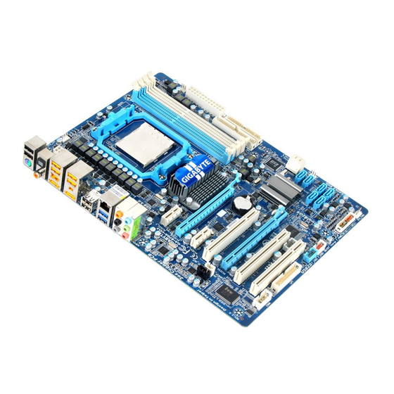
Page 10: Layout Diagram
ATA 133 IDE Conn (IDE1) SYSFAN2 Audio Connector 4-pin PWR Connector Gigabit LAN Chip AMD SB 850 Chipset 16 MBit SMT Flash PCI Express 2.0 x16 Mini-PCI Express Slot ROM BIOS by 8-lane Slot Clear CMOS (JBAT) PCI Express 2.0 x1 Slots... - Page 11 Jumpers Jumper Name Description KB/USB Power On Enabled/Disabled 3-pin Block JBAT Clear CMOS Header 2-pin Block Connectors Connector Name Description ATXPWR1 ATX Power Connector 24-pin Block ATX12V2 ATX 12V Power Connector 8-pin Block Power Connector 4-Pin Block KB from UK1 PS/2 Keyboard Connector 6-pin Female SPDIF_OUT1...
-
Page 12: Chapter 2 Hardware Installation
Chapter 2 Hardware Installation Turn off your power when adding or removing expansion cards or WARNING! other system components. Failure to do so may cause severe damage to both your motherboard and expansion cards. Hardware installation Steps Before using your computer, you had better complete the following steps: 1. -
Page 13: Install Cpu
Note: When should clear CMOS 1. Troubleshooting 2. Forget password 3. After over clocking system boot fail JBAT 1-2 Open: Normal 1-2 Short: CMOS Clear CMOS Clear Setting Install CPU 2-3-1 Glossary Chipset (or core logic) - two or more integrated circuits which control the interfaces between the system processor, RAM, I/O devises, and adapter cards. -
Page 14: About Amd Am3 Cpu Installation
2-3-2 About AMD AM3 CPU Installation This motherboard provides a socket AM3 surface mount, Zero Insertion Force (ZIF) socket, referred to as the mPGA socket supports AMD AM3 processor. The CPU that comes with the motherboard should have a cooling FAN attached to prevent overheating. -
Page 15: Expansion Cards
Dual channel Limited! Dual channel function only supports when 2 DIMM Modules plug in either both DDRIII 1 & DDRIII 2, or DDRIII 3 & DDRIII 4, or DDRIII 1~DDRIII 4 if installing 4 modules. Memory modules must be the same type, same size, and same frequency for dual channel function. -
Page 16: Expansion Slots
When PE4 installed switch card, the PE1 will doubled its bandwidth. Two PCI Express x1 I/O slot tackling the most demanding multimedia tasks nowadays. The AMD 870 motherboards also carry two 32-bit PCI slots and one mini-PCIE WIFIF card expansion slot to guarantee the rich connectivity for the I/O peripheral devices. -
Page 17: Connectors And Headers
2-6 Connectors and Headers 2-6-1 Connectors Power Connector (24-pin block): ATXPWR1 ATX Power Supply connector: This is a new defined 24-pins connector that usually comes with ATX case. The ATX Power Supply allows using soft power on momentary switch that connect from the front panel switch to 2-pins Power On jumper pole on the motherboard. - Page 18 This is a new defined 8-pins connector that usually comes with ATX Power Supply. The ATX Power Supply which fully supports Socket AM3 processor must including this connector for support extra 12V voltage to maintain system power consumption. Without this connector might cause system unstable because the power supply can not provide sufficient current for system.
- Page 19 The connectors are 4-pin connector that supports extra 12V / 5V power to your system (9) Primary IDE Connector (40-pin block): IDE1 This connector supports the provided IDE hard disk ribbon cable. After connecting the single plug end to motherboard, connect the two plugs at other end to your hard disk(s).
-
Page 20: Headers
(14) Coaxial/Optical SPDIF _OUT header: SPDIF_OUT1/SPDIF_OUT2 The SPDIF output is capable of providing digital audio to external speakers or compressed AC3 data to an external Dolby digital decoder. Use this feature only when your stereo system has digital input function. SPDIF_OUT1 (above) is coaxial SPDIF_OUT connector while SPDIF_OUT2 (below) is optical SPDIF_OUT connector. - Page 21 (3) Speaker connector: SPEAKER1 This 4-pin connector connects to the case-mounted speaker. See the figure below. (4) Power LED: PWR LED1/ PWR LED The Power LED is light on while the system power is on. Connect the Power LED from the system case to this pin. (5) Hard disk Activity LED: HD LED This connector connects to the hard disk activity indicator light on the case.
- Page 22 (9) CD Audio-In Headers (4-pin): CDIN1 CDIN are the connectors for CD-Audio Input signal. Please connect it to CD-ROM CD-Audio output connector. CDIN CD Audio-In Headers (10) IR infrared module Headers (5-pin): IR1 This connector supports the optional wireless transmitting and receiving infrared module.
- Page 23 Pin 1 PARALLEL Connector (13) HDMI-SPDIF Out header: HDMI_SPDIF The SPDIF output is capable of providing digital audio to external speakers or compressed AC3 data to an external Dolby digital decoder. Use this feature only when your stereo system has digital input function. Some of the VGA Card need connect SPDIF-IN Connector,so its HDMI Port can make sounds .
-
Page 24: Starting Up Your Computer
Starting Up Your Computer 1. After all connections are made, close your computer case cover. 2. Be sure all the switch are off, and check that the power supply input voltage is set to proper position, usually in-put voltage is 220V∼240V or 110V∼120V depending on your country’s voltage used. -
Page 25: Chapter 3 Introducing Bios
Chapter 3 Introducing BIOS The BIOS is a program located on a Flash Memory on the motherboard. This program is a bridge between motherboard and operating system. When you start the computer, the BIOS program will gain control. The BIOS first operates an auto-diagnostic test called POST (power on self test) for all the necessary hardware, it detects the entire hardware device and configures the parameters of the hardware synchronization. -
Page 26: The Main Menu
Press F1 to pop up a small help window that describes the appropriate keys to use and the possible selections for the highlighted item. To exit the Help Window, press <Esc>. The Main Menu Once you enter AMI BIOS Setup Utility, the Main Menu (Figure 3-1) will appear on the screen. -
Page 27: Standard Bios Features
This menu uses a minimal performance setting, but the system would run in a stable way. BIOS Security Features This entry for setting Supervisor password and User password Save Changes and Exit Save CMOS value changes to CMOS and exit setup. Discard Changes and Exit Abandon all CMOS value changes and exit setup. -
Page 28: Advanced Bios Features
DMA MODE: the optional settings are Auto, SWDMAn, MWDMAn , UDMAn. This option allows you to enable the HDD S.M.A.R.T Capability S.M.A.R.T.: (Self-Monitoring, Analysis and Reporting Technology). The optional settings are Auto; Disabled; and Enabled. 32 Bit Data Transfer: the optional settings are: Disabled and Enabled. Floppy A This item is for specific floppy disk drive settings. -
Page 29: Cpu Configuration
3-5-1 CPU Configuration Secure Virtual Machine Mode Enable/disable Secure Virtual Machine Mode (SVM). CIE Support The optional settings are Enabled and Disable. Advanced Chipset Features The Advanced Chipset Features Setup option is used to change the values of the chipset registers. These registers control most of the system options in the computer. Primary Video Controller This item is for user to choose primary video controller. -
Page 30: Pci Express Configuration
3-6-1 PCI Express Configuration GFX Dual Slot Configuration The optional settings are: Auto; Enable; and Disabled. Port #02 Features ~ Port #03 Features Press Enter and set values in the sub-items as: Gen2 High Speed Mode; Link ASPM; Link Width and Slot Power Limit, W. etc. . Port #04 Features~ Port #10 Features Press Enter and set values in the sub-items as Gen2 High Speed Mode, and Link ASPM. -
Page 31: Power Management Features
OnChip SATA Channel Press Enter to enable or disable CnChip SATA Channel. 0nChip SATA Type Press Enter to select the SATA type. The optional settings are: Native IDE; RAID; AHCI; Legacy IDE. 0nChip IDE Type The optional settings are Legacy IDE and Native IDE. Onboard PCI E Lan Use this item to enable or disable Onboard PCI E Lan. -
Page 32: Miscellaneous Configuration
Suspend mode Use this item to select the ACPI state used for system suspend. The optional settings are: S1 (POS); S3 (STR). Power On by PCIE (WOL)/ Keyboard/ Mouse The optional settings are: Enabled; Disabled. 3-9 Miscellaneous Control Clear NVRAM Clear NVRAM during System Boot. -
Page 33: Pc Health
Allocate IRQ for PCI VGA The optional settings are: No; Yes. Yes: Assigns IRQ to PCI VGA card if card requests IRQ. No: Does not assign IRQ to PCI VGA card even card requests an IRQ. Palette Snooping The optional settings are: Enabled; Disabled. Enable: inform the PCI device that an ISA graphics devices is installed in the system so the card will function correctly. -
Page 34: Power User Overclock Setting
3-11 Power User Overclock Setting Core Enhancer Use this item to enable or disable CPU core enhancer function. Please notice there are risks to be consider to split core. CPU/HT Reference Clock Use this item to set CPU/HT Reference Clock. The optional setting range is:190~600 MHz. - Page 35 clock and this board is capable.The optional setting range is:Auto; 200MHz to 2.6GHz Link Width The Hyper Transport link will run at the width selected. The optional setting range is:Auto; 4 Bit,8 Bit, 16Bit. PCI E Reference Clock (MHz) The optional setting range is: 90~250 MHz. SB Reference Clock (MHz) The optional setting range is: 90~150 MHz.
-
Page 36: Memory Configuration
3-11-1 Memory Configuration DRAM Timing Mode The optional settings are: Auto; DCT0, DCT1 and Both. Bank Interleaving Use this item to enable bank memory interleaving. Channel Interleaving The optional settings: Disabled; Address bits 6; Address bits 12; XOR of Address bits [20:16,6];... -
Page 37: Bios Security
3-12 BIOS Security Features You can set either supervisor or user password, or both of them. The differences are: Supervisor password: Can enter and change the options of the setup menus. Can only enter but do not have the right to change the options User password: of the setup menus. -
Page 38: Load Optimal/Failsafe Defaults
boot sector protection. If this function is enabled and someone attempt to write data into this area, BIOS will show a warning message on screen and alarm beep. Disabled (default) No warning message to appear when anything attempts to access the boot sector or hard disk partition table. Activates automatically when the system boots up causing a warning Enabled message to appear when anything attempts to access the boot sector of hard disk... - Page 39 Pressing <OK> to leave BIOS setting without saving previously set values. Notice! The BIOS options in this manual are for reference only. Different configurations may lead to difference in BIOS screen and BIOS screens in manuals are usually the first BIOS version when the board is released and may be different from your purchased motherboard .
-
Page 40: Chapter 4 Driver & Free Program Installation
Chapter 4 Driver & Free Program Installation Check your package and there is A MAGIC INSTALL CD included. This CD consists of all DRIVERS you need and some free application programs and utility programs. In addition, this CD also include an auto detect software which can tell you which hardware is installed, and which DRIVERS needed so that your system can function properly. -
Page 41: Ati Install Ati Integrated Driver Pack
4-1 ATI Install ATI Integrated Drive Pack 1. Click ATI when Magic Install menu appears. 2. Click” Next” on the welcome menu. 3. Click “Yes” to accept the license 4. Select if you wish to restart the computer agreement. now , then click “Finish”. 4-2 SOUND Install ALCHD Audio Codec Driver 1. -
Page 42: Lan Install Gigabit Ethernet Nic Driver
3. Click “Finish” and restart your computer. 4. Manual Sound Effect Setting. 5. Mixer setting. 6. Audio input and output setting. 7. Microphone effect setting. 8. 3D demo setting. 4-3 LAN Install Gigabit Ethernet NIC Driver 1 Click LAN when Magic Install Menu appears. 2. Click “Next” to install LAN and Fast Ethernet NIC Driver. -
Page 43: Usb3.0 Install Usb3.0 Driver
3 Click “install” to begin the installation. 4. Installation completed, Click “Finish”. 4-4 USB3.0 Install USB3.0 Driver 1 Click USB3.0 when Magic Install Menu 2. Click “Next” to continue. appears. 3 Click “I accept the terms of the license 4. Select folder where setup will install files, Click agreement”, then click “Next”. -
Page 44: Raiddisk Install Ati Sata Driver And Utility
5. Click “install” to begin the installation. 6. Installation completed, Click “Finish”. 4-5 RAIDDISK Install ATI SATA Driver and Utility 1 Click RAIDDisk when Magic Install menu 2. Copy the files to floppy disk and restart appears the computer with floppy disk as the first booting disk and then follow the steps shown on the screen to finish RAID function settings. -
Page 45: How To Update Bios
Step 4. Type Enter to update and flash the BIOS. The system will restart automatically when BIOS is upgraded. 4-8 AMD Platform RAID Function Installation Please set these choice in the BIOS as R AID:BIOS setup \Integrated Peripherals \OnChip SATA Type. When the below figure1 appeared, please press [Ctrl-F] into... - Page 46 Press [1] key, showing the RAID, as the below figure [figure3] Press [2] key, the interface of RAID, as figure 4. RAID function: RAID 1/ RAID 0/ RAID 10 / RAID5/JBOD [figure4] Press [Ctrl+C] to building RAID. as the below figure:...
- Page 47 Take Raid0 for example, use [↑] [↓] to shift the cursor, press space key to change the choice, press [Ctrl-Y] to save. Set Assignment mode as [Y], press [Ctrl-Y] to save, and then figure 5 appeared. It will reminds you to press [Ctrl-Y] to input the LD name, as the below figure 6; press [Ctrl-Y] to save and enter the below figure 7;...
- Page 48 [figure7] [figure 8] Press [3]; delete the RAID mode, press [Delete] or [Alt+D] will delete the array. As Figure 9. [figure9] Press [4], showing the information of controller, as figure 10.
- Page 49 OS. 2: After booting OS insert the bundle CD in your CD-ROM 3: Copy all the files from\AMD\RAIDDisk to floppy diskette Once you have the SATA driver diskette ready, you may start to install Windows OS on your System.
-
Page 50: Function Led Display
4-9 G.P.I. Function LED Display SSP_LED4 When the LED is off or glitters. It means the motherboard in the G.P.I mode. CPU works with the low power consumption. SSP_LED4 When the LED is on. It means the motherboard is working at full-speed with non- power saving mode. -
Page 51: Appendix
Regarding the Application of 3-Phase or 3+1 Phase Power Supply Mold As a result of the increasing power consumption demand from many AMD CPUs in current market, we suggest not to use a CPU that demands more than 65W power consumption at work for an AMD CPU compliant board that comes with... - Page 52 Both the amount of electric current to MOSFET and the heat produced from the motherboard go up as AMD’s CPU power consumption increases. In this case we recommend users select a CPU fan with air outlet towards MOSFET so that CPU fan can carry away heat produced by MOSFET, for better heat dissipation effects.
Need help?
Do you have a question about the 870 and is the answer not in the manual?
Questions and answers